Multidirectional double-drive rail guide vehicle

A dual-drive shuttle and wheel technology, which is applied in the field of shuttles, can solve the problems of unable to drive the shuttle to run normally, unable to adapt to complex working environments, and not having steering functions, so as to increase the utilization rate of warehouse space and improve the warehouse space. Utilization, the effect of increasing the diversity of layout

Pending Publication Date: 2017-05-31
TAIYUAN OTTLE LOGISTICS TECH CO LTD
View PDF13 Cites 1 Cited by
  • Summary
  • Abstract
  • Description
  • Claims
  • Application Information

AI Technical Summary

Problems solved by technology

[0002] At present, the shuttle vehicles used in warehousing and logistics equipment are divided into linear reciprocating shuttle vehicles and circular motion shuttle vehicles. Linear reciprocating shuttle vehicles do linear motion without steering function. The disadvantage is that the operating line is relatively single and the degree of automation is not high.
The circular motion shuttle runs on the elliptical double track, and the driving wheel is installed on the outer ring guide rail to realize the direction change. However, this kind of direction change is single. It is assumed that once the direction is changed, the driving wheel will change from the outer ring guide rail to the inner ring guide rail. As a result, the power is insufficient to drive the shuttle car to run normally. If the single drive is upgraded to multi-drive, there will be a linear speed difference between the rollers.
Therefore, none of the current shuttle vehicles can adapt to the complex working environment

Method used


Image

  • Multidirectional double-drive rail guide vehicle
  • Multidirectional double-drive rail guide vehicle
  • Multidirectional double-drive rail guide vehicle

Examples


Embodiment Construction

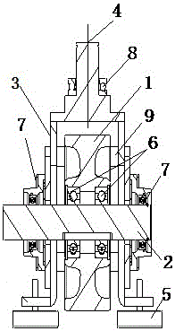
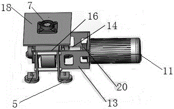
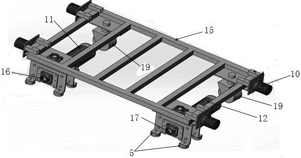
[0013] The main drive system comprises a main motor 11, a support 13, an electromagnetic brake 20, a shaft coupling 14, a front driving wheel 16, a mounting plate 18 and a bearing with seat 7; The main motor 11 housing is fixed, and the other end of the bracket 13 is fastened on the front driving wheel 16; the main motor 11 is fixed by the bracket 13, and the output shaft of the main motor 11 is connected with the shaft of the front driving wheel 16 through a coupling 14; the electromagnetic brake 20 is installed on the output shaft of the main motor 11; the mounting plate 18 is a flat plate with a mounting hole in the center, and the mounting plate 18 is horizontally installed on the top of the front driving wheel 16, and the mounting plate 18 and the car body 15 are welded and fixed; the front driving wheel 16 Including wheel 1 and wheel axle 2, wheel side plate 3 and top plate, guide rail stop wheel 5 and stop bar 9; wheel side plate 3 is two flat plates located on both side...


PUM


Abstract

The invention provides a multidirectional double-drive rail guide vehicle which aims to achieve small friction resistance and convenient and flexible turning. The multidirectional double-drive rail guide vehicle comprises a main drive system, an auxiliary drive system, two driven wheels, a vehicle body and buffers. The main drive system comprises a main motor, a support, an electromagnetic brake, a coupler, a front driving wheel, an installation plate and a mounted bearing. An output shaft of the main motor is connected with a shaft of the front driving wheel through the coupler. The electromagnetic brake is installed on the output shaft of the main motor. The front driving wheel comprises a wheel, an axle, a wheel side plate, a top plate, a guide rail stopping wheel and a stopping rod. The guide rail stopping wheel is horizontally installed at the lower end of the wheel side plate. The guide rail stopping wheel is perpendicular to the position of the wheel. The auxiliary drive system is identical with the main drive system in structure, but a one-way bearing is installed at the center of a wheel of a back driving wheel coaxially and reversely in an engaged and disengaged manner. The main drive system and the auxiliary drive system are distributed at the front end and the back end of the same side of the vehicle body correspondingly. The front end and the back end of the other side of the vehicle body are provided with the two driven wheels corresponding to the wheels of the front driving wheel and the back driving wheel in position.

Description

technical field [0001] The invention relates to a shuttle car used for warehousing and logistics running on a transport track, in particular to a shuttle car running in a complex environment. Background technique [0002] At present, the shuttle vehicles used in warehousing and logistics equipment are divided into linear reciprocating shuttle vehicles and circular motion shuttle vehicles. Linear reciprocating shuttle vehicles do linear motion without steering function. The disadvantage is that the operating line is relatively simple and the degree of automation is not high. The circular motion shuttle runs on the elliptical double track, and the driving wheel is installed on the outer ring guide rail to realize the change of direction. However, this kind of direction change is single. It is assumed that once the direction is changed, the driving wheel will change from the outer ring guide rail to the inner ring guide rail. As a result, the power is insufficient to drive the ...

Claims


Application Information

Patent Timeline
Patent Type & Authority Applications(China)
IPC IPC(8): B65G1/04
CPCB65G1/0492
Inventor 王磊韩二占成燕燕徐腾飞姚传彪徐晓媛
Owner TAIYUAN OTTLE LOGISTICS TECH CO LTD
Why Eureka
Try Eureka