
Workbench of carving machine

A technology of workbench and engraving machine, which is applied to engraving, painting tools, processing models, etc., can solve problems such as difficulty in ensuring the alignment of wood boards, movement of processed parts, and low efficiency, so as to improve processing efficiency and reduce labor intensity degree, the effect of expanding the operating area

Active Publication Date: 2017-05-31
重庆汇升套装门有限公司
View PDF4 Cites 2 Cited by
  • Summary
  • Abstract
  • Description
  • Claims
  • Application Information

AI Technical Summary

Problems solved by technology

The disadvantages of the existing workbench of this engraving machine are as follows: (1) it is inconvenient to center and fix the plank, relying on manual clamping, the efficiency is low
Since the workpiece to be processed is only fixed by the manual clamping block at the clamping groove, it is difficult to ensure whether the plank is centered, and the workpiece to be processed is not fixed firmly, and loosening phenomena such as movement and twisting of the workpiece are prone to occur, which greatly affects The engraving quality of the workpiece is improved; (2) the scope of application is narrow
The setting position of the clamping groove on the mechanical press-fit table is limited, so some workpieces do not match the clamping position due to the length or width of the workpiece, so that some workpieces cannot be fixed, so it is also It is impossible to process these mismatched workpieces, and the scope of application is narrow

Method used


Image

  • Workbench of carving machine
  • Workbench of carving machine
  • Workbench of carving machine

Examples


Embodiment Construction

[0016] The present invention will be described in further detail below by means of specific embodiments:

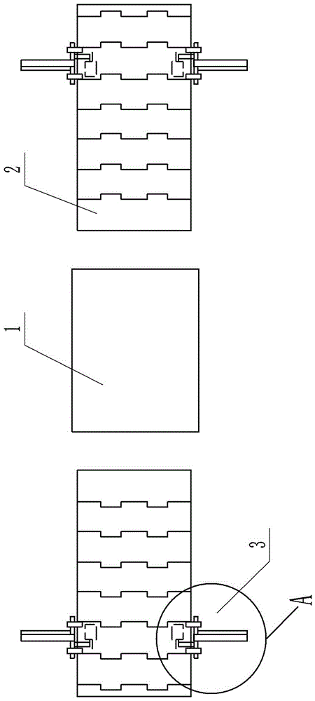
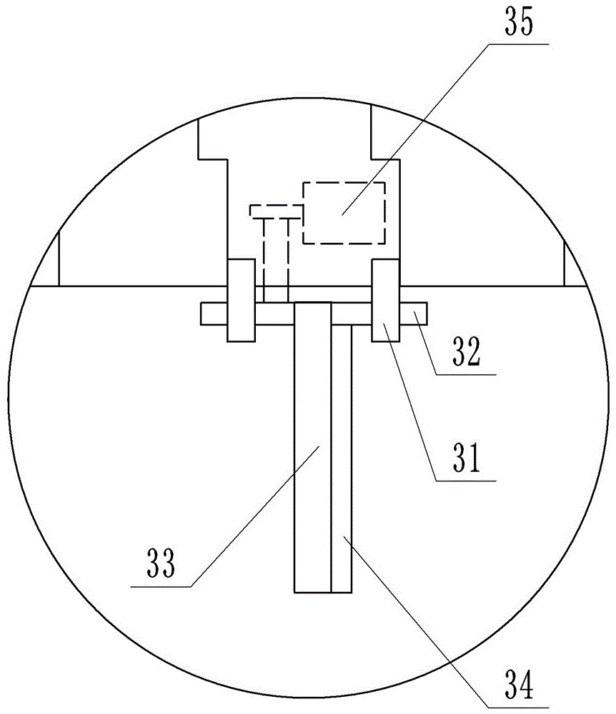
[0017] The reference signs in the drawings of the description include: workbench 1, chain plate conveyor 2, roller 21, chain plate conveyor belt 22, flip clamping mechanism 3, fixed seat 31, rotating shaft 32, limit plate 33, fixed plate 34, The second servo motor 35, the first servo motor 4.

[0018] Such as figure 1 As shown, the workbench 1 of the engraving machine includes a workbench 1, a first servo motor 4 and a chain plate transmission device 2. There are two chain plate transmission devices 2, which are respectively located on both sides of the workbench 1; the first servo motor The output shaft of 4 is connected with the workbench 1, and is used to drive the workbench 1 to rotate. Such as figure 2 As shown, the chain conveyor device 2 includes a roller 21, a chain conveyor belt 22 and two turning clamping mechanisms 3, and the turning clamping mechanisms 3 a...


PUM


Abstract

The invention belongs to the technical field of carving machine equipment, and particularly discloses a workbench of a carving machine. The workbench comprises a workbench body, a first servo motor driving the workbench body to rotate, and chain plate conveying devices arranged on the two sides of the workbench body. Each chain plate conveying device comprises chain wheels, a chain plate conveying belt and an overturning and clamping mechanism fixed to the side edge of the chain plate conveying belt, wherein the chain plate conveying belt is driven through the wheels, and the height of the chain plate conveying belt is equal to the height of the workbench body. Each overturning and clamping mechanism comprises a rotating shaft, a second servo motor, a limiting plate and fixing bases, wherein the fixing bases are arranged at the two ends of the rotating shaft correspondingly and fixed to the side edge of the chain plate conveying belt; an output shaft of the second servo motor is rotationally connected with the rotating shaft through a belt; and the limiting plate is fixedly arranged on the rotating shaft. The workbench can effectively conduct centering fixing on a wood board, the two ends of the wood board are tightly clamped through the limiting plates, fixing is firm, and moving, twisting or other loosening phenomena of the wood board are not likely to happen.

Description

technical field [0001] The invention belongs to the technical field of engraving machine equipment, and in particular relates to a working table of an engraving machine. Background technique [0002] With the development of modern construction, there are requirements for light weight, beautiful appearance and variety of decorative materials. Decorative wooden boards are usually artificially designed, carved or painted to achieve beautiful effects; they have the advantages of light weight, high strength, corrosion resistance, pollution resistance, convenient construction, and human-controlled patterns. They are ideal decorative materials for modern buildings. . [0003] The function of the engraving machine is to grind the surface or edge of the board into various styles according to the design requirements. At present, the workbench of the engraving machine generally includes a table top, which is provided with a clamping groove, and the table top is a mechanically pressed...

Claims


Application Information

Patent Timeline
Patent Type & Authority Applications(China)
IPC IPC(8): B44B1/06B44B3/06
CPCB44B1/06B44B3/06B44B2700/02B44B2700/04B44B2700/12
Inventor 颜静
Owner 重庆汇升套装门有限公司
Learn More