
Manipulator design method for installing mill lining

A design method and manipulator technology, applied in the direction of manipulators, program control manipulators, manufacturing tools, etc., can solve the problems of heavy grasping, removal, replacement and installation, inconvenient on-site replacement and installation, poor maintenance safety, etc., to improve work Efficiency and maintenance safety, improvement of labor intensity, effect of reducing labor intensity

Active Publication Date: 2017-05-31
LUOYANG CITIC HIC AUTOMATION ENG
View PDF4 Cites 0 Cited by
  • Summary
  • Abstract
  • Description
  • Claims
  • Application Information

AI Technical Summary

Problems solved by technology

In order to ensure the long-term continuous operation of the mill, liners are installed in the cylinder of the mill to prevent the cylinder from being worn out. Usually, the liner is divided into several pieces. These liners are often worn during use, and the liner needs to be worn Remove and replace the new liner in time. The size of the large horizontal mill liner is different. The weight of each liner is generally between 1000 and 5000kg. It needs to be grasped, removed and replaced. Very inconvenient to replace and install on site
[0003] Large-scale horizontal mills replace the liners manually. Workers remove the worn liners by making simple tools such as driving in the workshop and electric hoists, and put the new liners into the mill, and then manually put the new liners into the mill. The liner is installed to the corresponding position in the cylinder, the working environment is harsh, the labor intensity is extremely high, time-consuming and labor-intensive, and the maintenance safety is poor

Method used


Image

  • Manipulator design method for installing mill lining
  • Manipulator design method for installing mill lining
  • Manipulator design method for installing mill lining

Examples


Embodiment Construction

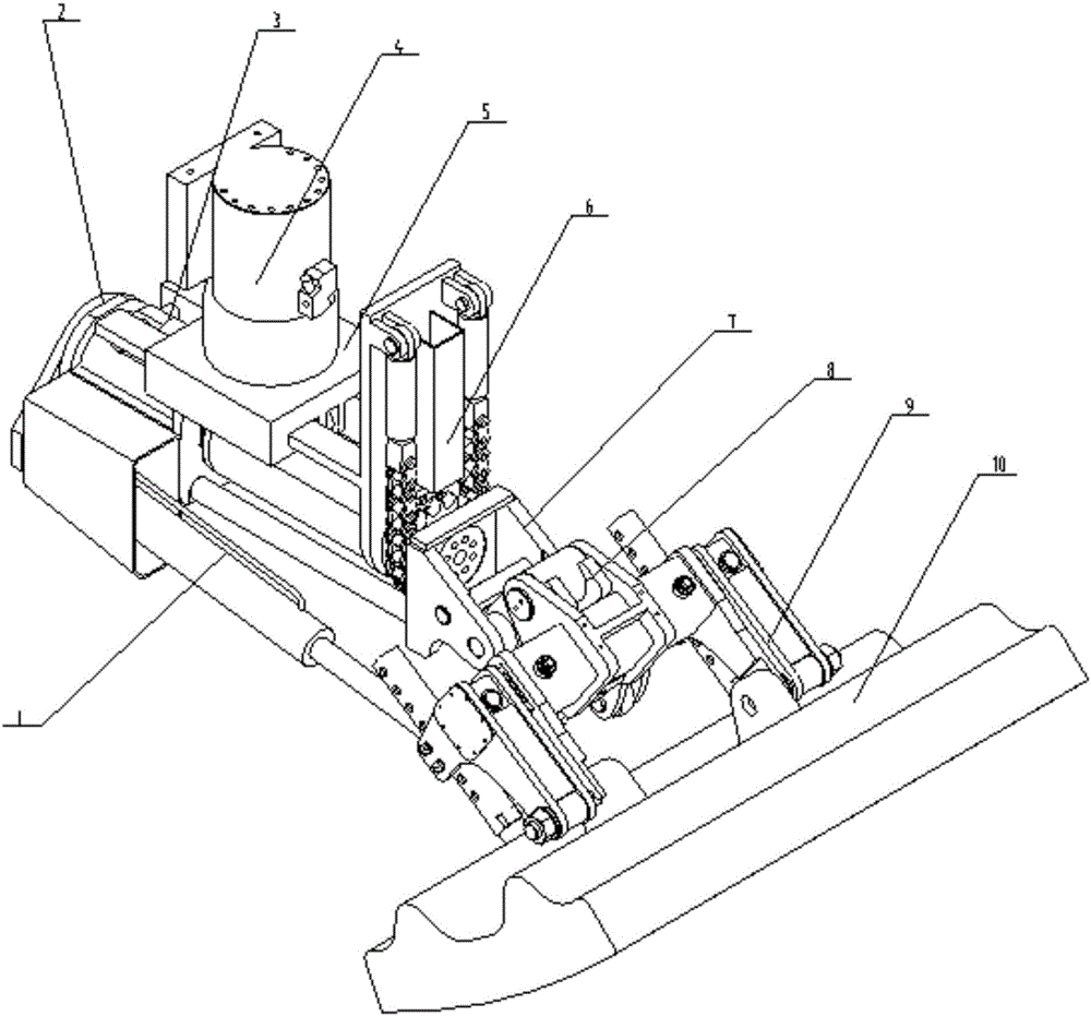
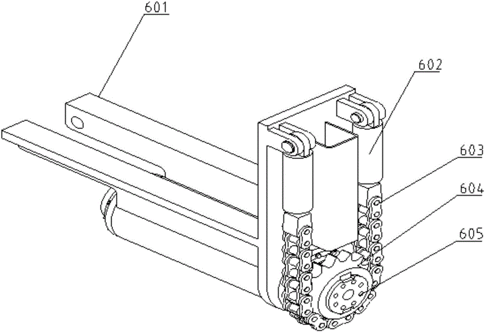
[0026] The present invention relates to a method for designing a manipulator for installing a mill liner. The manipulator is respectively designed with a rolling device, a grabbing device, other accessories and a first oil cylinder, a second oil cylinder, a third oil cylinder, The fourth oil cylinder, the swing oil cylinder, the first oil cylinder has the function of rolling joint in the rolling device, the second oil cylinder has the function of moving forward and backward, the third oil cylinder has the function of pitch joint, and the fourth oil cylinder has the function of grasping in the grabbing device. Joint action, the oscillating cylinder has an up and down swing joint action, and through these different joint actions, the manipulator can achieve multiple displacements in the spatial position.

[0027] combine Figure 1-4 , it is given that the board 10 to be relined has two lifting lugs with the same structure, the two lifting lugs are configured with lifting holes w...


PUM


Abstract

The invention provides a manipulator design method for installing a mill lining. A rolling pendulum device, a gripping device, other accessories and a first cylinder, a second cylinder, a third cylinder, a forth cylinder and a swinging cylinder fit to the accessories are designed in the manipulator, wherein the first cylinder has the rolling joint action in the rolling pendulum device, and the second cylinder has the joint action of back-and-forth movement; the third cylinder has the pitch joint action, and the forth cylinder has the gripping joint action in the gripping device; the swinging cylinder has the joint action of up-and-down swing; multiple displacements of the manipulator in space are achieved through these different joint actions, and the high-load drive of the manipulator is achieved through arranging these cylinders; the structure size of the manipulator is reduced. In the invention, the degree of mechanization and automation in the replacement of the mill lining is greatly improved, and the labor intensity is reduced; the replacement time of the lining is shortened, and potential safety hazards in manual operation are avoided.

Description

technical field [0001] The invention belongs to the technical field of mill liner maintenance equipment, in particular to a design method for a manipulator for installing a mill liner. Background technique [0002] The mill is divided into a ball mill or a semi-autogenous mill, which is the main equipment for mine grinding. In order to ensure the long-term continuous operation of the mill, liners are installed in the cylinder of the mill to prevent the cylinder from being worn out. Usually, the liner is divided into several pieces. These liners are often worn during use, and the liner needs to be worn Remove and replace the new liner in time. The size of the large horizontal mill liner is different. The weight of each liner is generally between 1000 and 5000kg. It needs to be grasped, removed and replaced. It is extremely inconvenient to replace and install on site. [0003] Large-scale horizontal mills replace the liners manually. Workers remove the worn liners by making ...

Claims


Application Information

Patent Timeline
IPC IPC(8): B25J9/04B25J9/14
CPCB25J9/048B25J9/148
Inventor 白云华胡同海孙富强刘贺伟唐孟阁权毅张亚琼赵红红赵纪锋
Owner LUOYANG CITIC HIC AUTOMATION ENG
Learn More