An automatic loading and unloading processing equipment with grinding function

A technology for automatic loading and unloading and processing equipment, which is applied in the direction of metal processing equipment, grinding/polishing equipment, grinding feed movement, etc., and can solve problems such as untreated workpiece burrs, inability to achieve workpiece clamping, and complicated equipment , to achieve the effects of high work efficiency, manpower saving and high degree of automation

Active Publication Date: 2018-12-14
沛县东明铸造有限公司
View PDF9 Cites 0 Cited by
  • Summary
  • Abstract
  • Description
  • Claims
  • Application Information

AI Technical Summary

Problems solved by technology

[0006] The purpose of the present invention is to provide a kind of automatic loading and unloading processing equipment with grinding function in view of the deficiencies of the prior art, which overcomes the problems that the automatic loading and unloading equipment in the machining process is relatively complicated, the cost is high and the loading cannot be realized. At the same time, it realizes the clamping of the workpiece and the problem that the burrs of the processed workpiece cannot be processed.

Method used


Image

  • An automatic loading and unloading processing equipment with grinding function
  • An automatic loading and unloading processing equipment with grinding function
  • An automatic loading and unloading processing equipment with grinding function

Examples


Embodiment 2

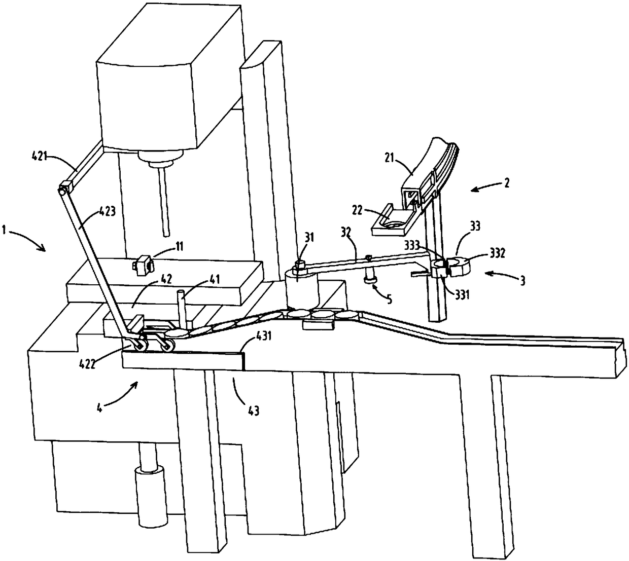
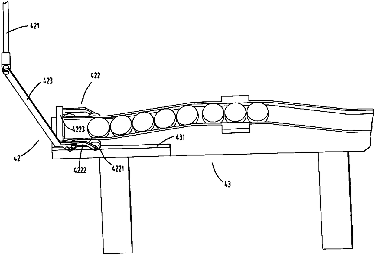
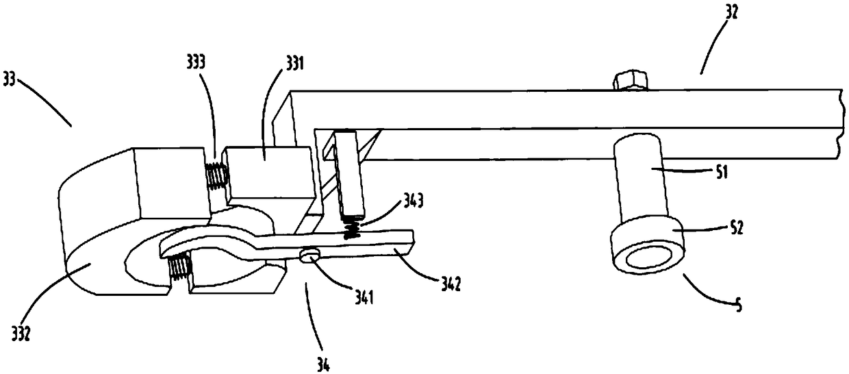
[0043] Such as figure 1 , figure 2 , image 3 , Figure 4 As shown, the components that are the same as or corresponding to those in the first embodiment are marked with the corresponding reference numerals in the first embodiment. For the sake of simplicity, only the differences from the first embodiment will be described below. The difference between the second embodiment and the first embodiment is that the pressing device 11 includes a fixed block 111, a screw 112 rotatably arranged on the fixed block 111, and a pressing block 113 fixed at the end of the screw 112; This arrangement of the device 11 makes the position of the pressing block 113 of the pressing device 11 adjustable, and the position of the pressing block 113 can be adjusted by turning the screw 112 according to the actual situation, so as to adjust the degree of tightness of the pressing block 113 against the moving clamp block 332 , can meet the clamping requirements of workpieces of different specificat...


PUM


Abstract

The invention relates to an automatic feeding and discharging machining device with a grinding function. The automatic feeding and discharging machining device with the grinding function comprises a machining device, a material supplying device, a feeding device and a discharging part, wherein the material supplying device comprises a material supplying track and a material falling device arranged at the outlet end of the material supplying track; the feeding device is used for receiving workpieces falling from the material falling device, and comprises a rotating device, a material arm with one end fixed to the rotating device, a material clamping device fixed to the end portion of the material arm, and a material supporting device rotationally arranged at the bottom of the material clamping device; and the discharging part comprises a shifting rod used in cooperation with the material supporting device. The automatic feeding and discharging machining device with the grinding function further comprises a grinding device arranged on the material arm and rotating along with the material arm; and the grinding device is used for grinding the surfaces of machined workpieces on a guiding groove. The automatic feeding and discharging machining device with the grinding function solves the problems that in the machining process, equipment achieving automatic feeding and discharging is complex, cost is high, the workpieces cannot be clamped while feeding is achieved, and burrs of the machined workpieces cannot be treated.

Description

technical field [0001] The invention belongs to the technical field of machining equipment, in particular to an automatic loading and unloading processing equipment with a grinding function. Background technique [0002] Existing processing equipment generally requires manual loading and operation of the clamping device to clamp the workpiece and then start the equipment to start processing. After processing, release the clamping device and then take out the processed workpiece. The efficiency is low, and the processed workpiece Workpieces often have burrs, which need to be removed later by other equipment or methods, and the workload is heavy. [0003] The authorized announcement number is a Chinese invention patent of CN102357660B, which discloses an automatic feeding lathe. Through the automatic feeding channel, the manipulator arranged above the table to be processed realizes the transportation of the workpiece on the table to be processed to the spindle close to the lat...

Claims


Application Information

Patent Timeline
Patent Type & Authority Patents(China)
IPC IPC(8): B24B41/00
CPCB24B41/00B24B41/005
Inventor 徐臻
Owner 沛县东明铸造有限公司
Why Eureka
Try Eureka