


Quick Research
Generate reliable direction feasibility study reports for your R&D in just a few steps.

Technical Q&A
Discover and master advanced knowledge NOW. Basics, ideas, possibilities, all at once.

Find Solutions
As an expert in R&D theories, this can generate solutions to your technical problems instantly.

Evaluate Feasibility
Analyze your overall solution with one click, know your potential R&D risks in advance.

Monitor Landscape
Get weekly tech updates, stay abreast of the latest tech innovations and key insights.
An orderly output processing device
A technology of processing equipment and conveying racks, which is applied in the direction of metal processing equipment, metal processing, metal processing machinery parts, etc., can solve the problems of easy injury to operators, difficult recycling of waste chips, and messy stacking of workpieces, etc., and achieves a high degree of automation, High work efficiency and orderly processing
- Summary
- Abstract
- Description
- Claims
- Application Information
AI Technical Summary
Problems solved by technology
Method used
Image

Examples
Embodiment 1
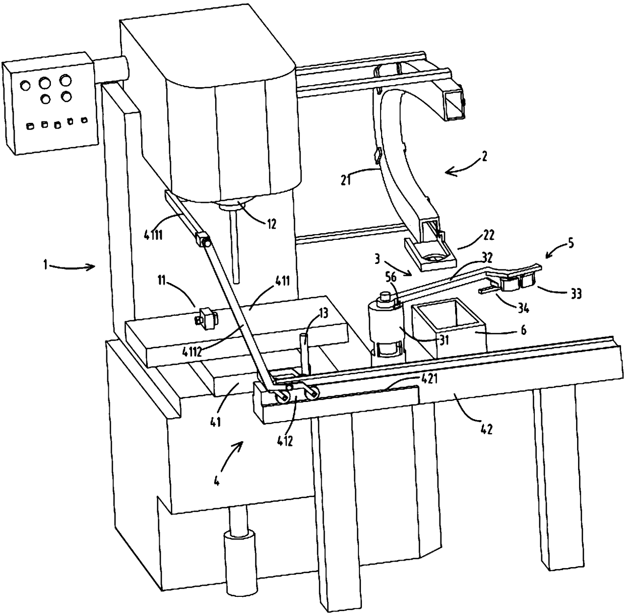
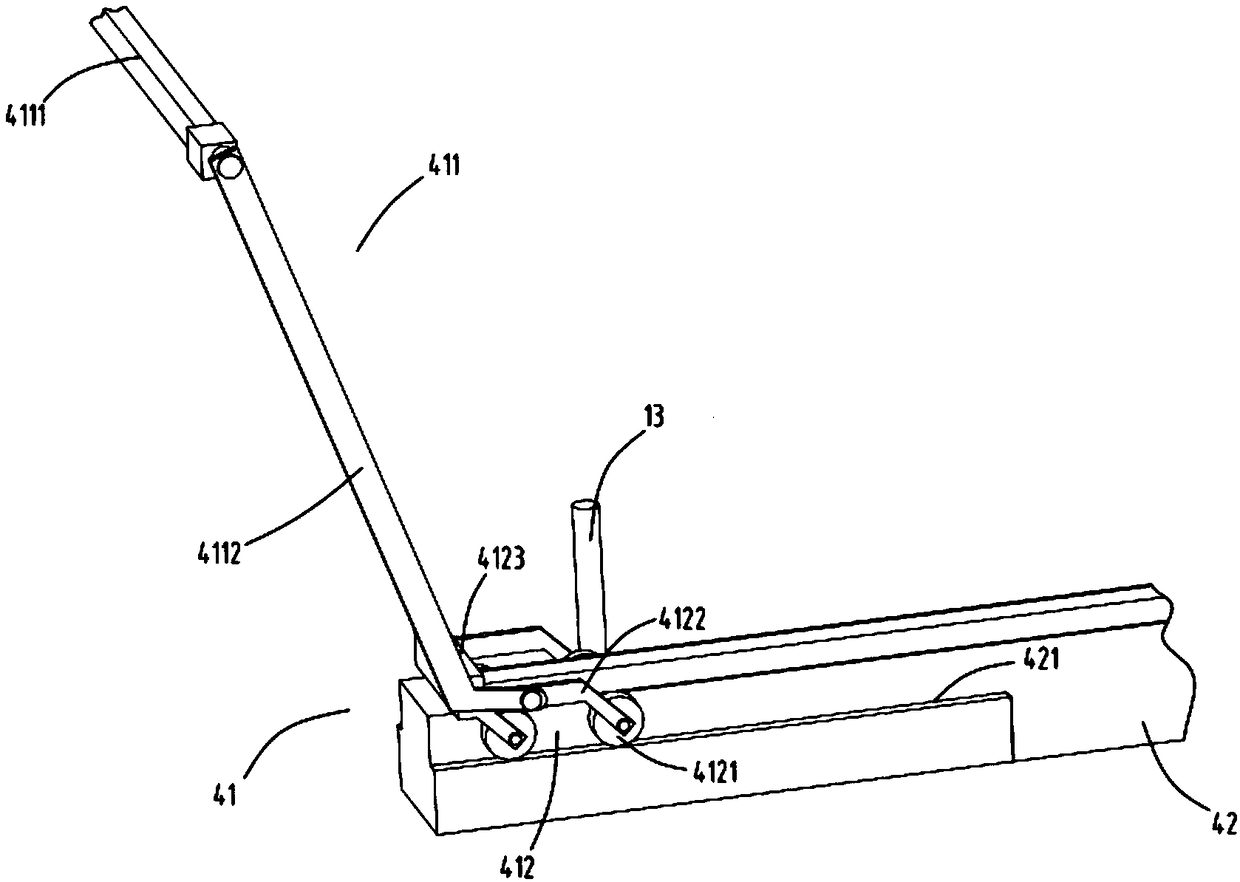
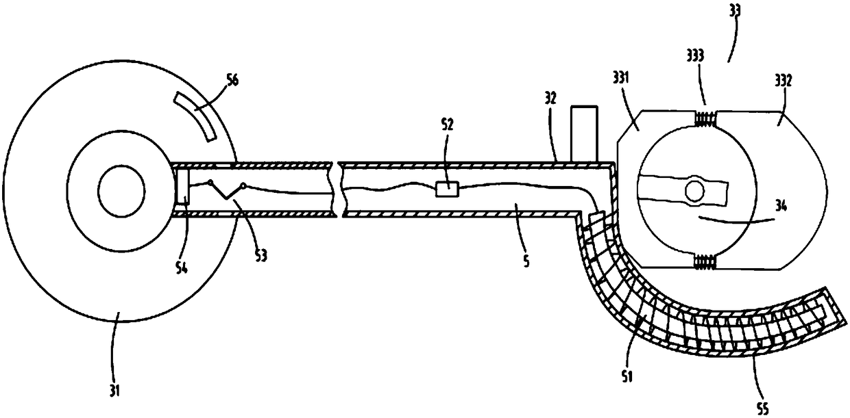
[0036] figure 1 is a schematic diagram of the ordered output processing equipment, figure 2 It is a schematic diagram of the structure of the discharge device, image 3 It is a schematic diagram of the structure of the electromagnetic adsorption device and the feeding device, Figure 4 It is a schematic diagram of the structure of the feeding part, Figure 5 It is a schematic diagram of the structure of the feeding device, Figure 6 It is a schematic top view of the discharge device, Figure 7 It is a schematic diagram of the structure of the pressing device. Such as figure 1 , figure 2 , image 3 , Figure 4 , Figure 5 , Figure 6 and Figure 7 As shown, what is provided in this embodiment is a kind of orderly output processing equipment, including processing equipment 1, feeding device 2, feeding device 3 and discharging device 4; The material rack 32 that the rotating device 31 rotates, the clamp 33 fixed on the end of the material rack 32, and the material h...
Embodiment 2
[0047] Such as figure 1 , figure 2 , image 3 , Figure 4 , Figure 5 , Figure 6 and Figure 7 As shown, the components that are the same as or corresponding to those in the first embodiment are marked with the corresponding reference numerals in the first embodiment. For the sake of simplicity, only the differences from the first embodiment will be described below. The difference between the second embodiment and the first embodiment is that the pressing device 11 includes a fixed block 111, a screw 112 rotatably arranged on the fixed block 111, and a pressing block 113 fixed at the end of the screw 112. According to the actual situation, the position of the pressure block 113 can be adjusted by turning the screw rod 112 to achieve different extrusion forces on the movable clamp block 332, which can meet the clamping requirements of workpieces of different specifications and sizes.
Embodiment 3
[0049] Such as figure 1 , figure 2 , image 3 , Figure 4 , Figure 5 , Figure 6 and Figure 7 As shown, the parts that are the same as or corresponding to those in the second embodiment are marked with the corresponding reference numerals in the second embodiment. For the sake of simplicity, only the differences from the second embodiment will be described below. The difference between the third embodiment and the second embodiment is that one end of the push-pull rod 4112 is rotatably fixed at the middle position of the side bracket 4122 of the rolling device 412, and this arrangement can ensure the stability of the rolling device during the push-pull process. Of course, this is based on the fact that the rolling device 412 will not be lifted off the slide rail 421 as a whole during the sliding process. It should be noted that the rolling device 412 has a certain mass. Will not be lifted off track 421.
[0050] Working process: feeding device 3 feeds material at the...
PUM
 Abstract
Description
Claims
Application Information
 - R&D Engineer
- R&D Manager
- IP Professional
- Industry Leading Data Capabilities
- Powerful AI technology
- Patent DNA Extraction
Browse by: Latest US Patents, China's latest patents, Technical Efficacy Thesaurus, Application Domain, Technology Topic, Popular Technical Reports.
© 2024 PatSnap. All rights reserved.Legal|Privacy policy|Modern Slavery Act Transparency Statement|Sitemap|About US| Contact US: help@patsnap.com