
Lifting type machine tool cutter detection device

A detection device, a lifting technology, applied in the direction of manufacturing tools, measuring/indicating equipment, metal processing machinery parts, etc., can solve the problems of increased production cost, large size of the mother machine, disadvantageous anti-cutting fluid and anti-iron filings, etc., to achieve isolation Cutting fluid and iron filings, good working environment, reliable protection effect

Inactive Publication Date: 2017-05-31
NINGBO HAITIAN PRECISION MASCH CO LTD
View PDF7 Cites 1 Cited by
  • Summary
  • Abstract
  • Description
  • Claims
  • Application Information

AI Technical Summary

Problems solved by technology

The existing machine tool detection device has a relatively simple structure and usually has two forms: one is to install the tool detection device with simple protection outside the workbench processing area. This simple protection is not conducive to preventing cutting fluid and iron filings , the protection effect is poor, which will reduce the service life of the tool detection equipment; the other is to install the tool detection device under the side of the workbench, and use the protection of the main machine to prevent cutting fluid and iron filings, but this protection It is necessary to increase the protective dimension of the side of the workbench of the main machine, and at the same time, it is necessary to add a power mechanism to drive the automatic door, resulting in a large volume of the main machine, which is not conducive to saving space and greatly increases the production cost

Method used


Image

  • Lifting type machine tool cutter detection device
  • Lifting type machine tool cutter detection device
  • Lifting type machine tool cutter detection device

Examples


Embodiment Construction

[0012] The present invention will be further described in detail below in conjunction with the accompanying drawings and embodiments.

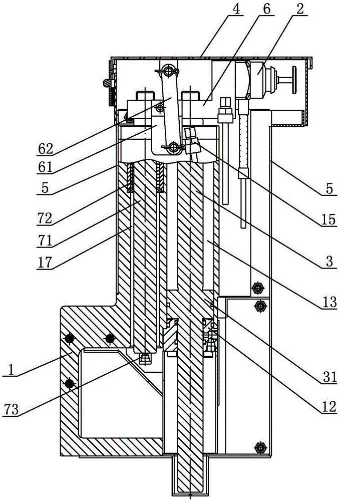
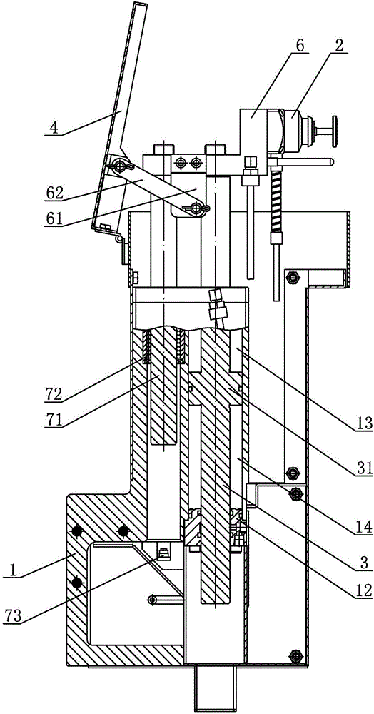
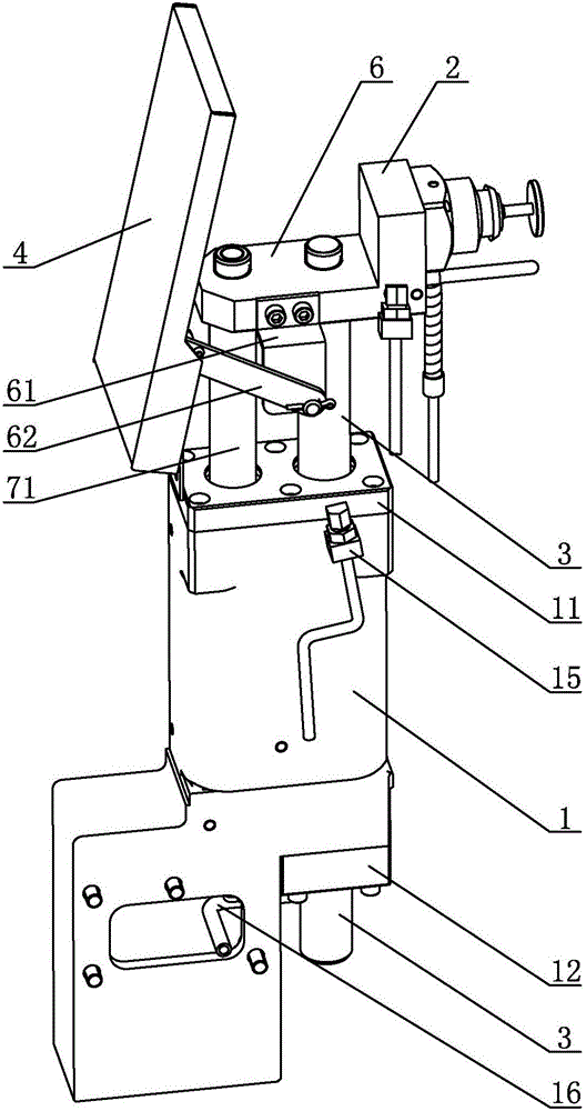
[0013] The lifting type machine tool detection device of the embodiment, such as Figure 1 ~ Figure 3 As shown, it includes a box body 1, a tool setting instrument 2, a piston rod 3, a waterproof cover 4 and a protective cover 5. The box body 1 is installed outside the processing area of ​​the machine tool (not shown in the figure), and the box body 1 is provided with The first installation hole, the piston rod 3 is installed upright in the first installation hole, the upper end of the first installation hole is equipped with an upper cylinder cover 11, the lower end of the first installation hole is equipped with a lower cylinder cover 12, and the upper end of the piston rod 3 is from the top The cylinder head 11 passes through, and the lower end of the piston rod 3 passes through the lower cylinder head 12. The middle part of the piston rod ...


PUM


Abstract

The invention discloses a lifting type machine tool cutter detection device. A piston rod and an installation plate form a lifting portion, and the piston rod, an upper cylinder cover and a lower cylinder cover form a piston air cylinder structure. When the device works, the air cylinder is adopted for driving, due to vertical motion of the piston rod, and the purpose of lifting the installation plate and a tool setting gauge is achieved. When the piston moves upwards, under the drive of a connecting rod, a waterproof cover located on the tool setting gauge is opened, the installation plate and the tool setting gauge stretch out of a protective cover, and the corresponding cutter detection operation can be performed; when the piston rod moves downwards, the installation plate and the tool setting gauge are driven to fall back into the protective cover, and the connecting rod drives the waterproof cover to be closed and to cover the protective cover. The waterproof cover and the connecting rod form a connecting rod driven mechanism, the connecting rod can move vertically along with the installation plate, the structure is simple, and protection is reliable.

Description

technical field [0001] The invention relates to a machine tool tool detection device, in particular to a lifting type machine tool tool detection device. Background technique [0002] With the rapid development of the manufacturing industry and the continuous updating of technology, higher requirements are put forward for machining equipment, and the precision requirements of machining equipment are constantly increasing. Many machine tools have begun to be equipped with tool detection devices to increase tool measurement functions. The existing machine tool detection device has a relatively simple structure and usually has two forms: one is to install the tool detection device with simple protection outside the workbench processing area. This simple protection is not conducive to preventing cutting fluid and iron filings , the protection effect is poor, which will reduce the service life of the tool detection equipment; the other is to install the tool detection device unde...

Claims


Application Information

Patent Timeline
Patent Type & Authority Applications(China)
IPC IPC(8): B23Q17/22B23Q11/08
CPCB23Q17/22B23Q11/0833
Inventor 陈小光黄继力
Owner NINGBO HAITIAN PRECISION MASCH CO LTD
Learn More