Eureka AIR delivers breakthrough ideas for toughest innovation challenges, trusted by R&D personnel around the world.

Automatic assembly machine for snap ring bearing fan blades of rotor

An automatic assembly machine and fan blade technology, applied in assembly machines, metal processing equipment, metal processing and other directions, can solve the problem of time-consuming production, and achieve the effect of reducing production man-hours, convenient operation, and good fan blade assembly.

Inactive Publication Date: 2018-12-11
馆陶县鑫荣轴承有限公司
View PDF5 Cites 0 Cited by
  • Summary
  • Abstract
  • Description
  • Claims
  • Application Information

AI Technical Summary

Problems solved by technology

[0003] Most of the existing rotor snap rings, bearings and fan blades are assembled step by step. The assembly line is operated through multiple assembly equipment. The fan blades are first assembled by the fan blade assembly device, and then the rotor is taken out and put into the pressure ring. The snap ring is assembled at the bottom of the device, and then the rotor is taken out and put into the bearing assembly device for bearing assembly. During the whole process, the rotor needs to be picked and placed and positioned many times, which consumes a lot of production man-hours

Method used


Image

  • Automatic assembly machine for snap ring bearing fan blades of rotor
  • Automatic assembly machine for snap ring bearing fan blades of rotor
  • Automatic assembly machine for snap ring bearing fan blades of rotor

Examples


Embodiment Construction

[0027] In order to enable those skilled in the art to better understand the technical solution of the present invention, the present invention will be described in detail below in conjunction with the accompanying drawings. The description in this part is only exemplary and explanatory, and should not have any limiting effect on the protection scope of the present invention. .

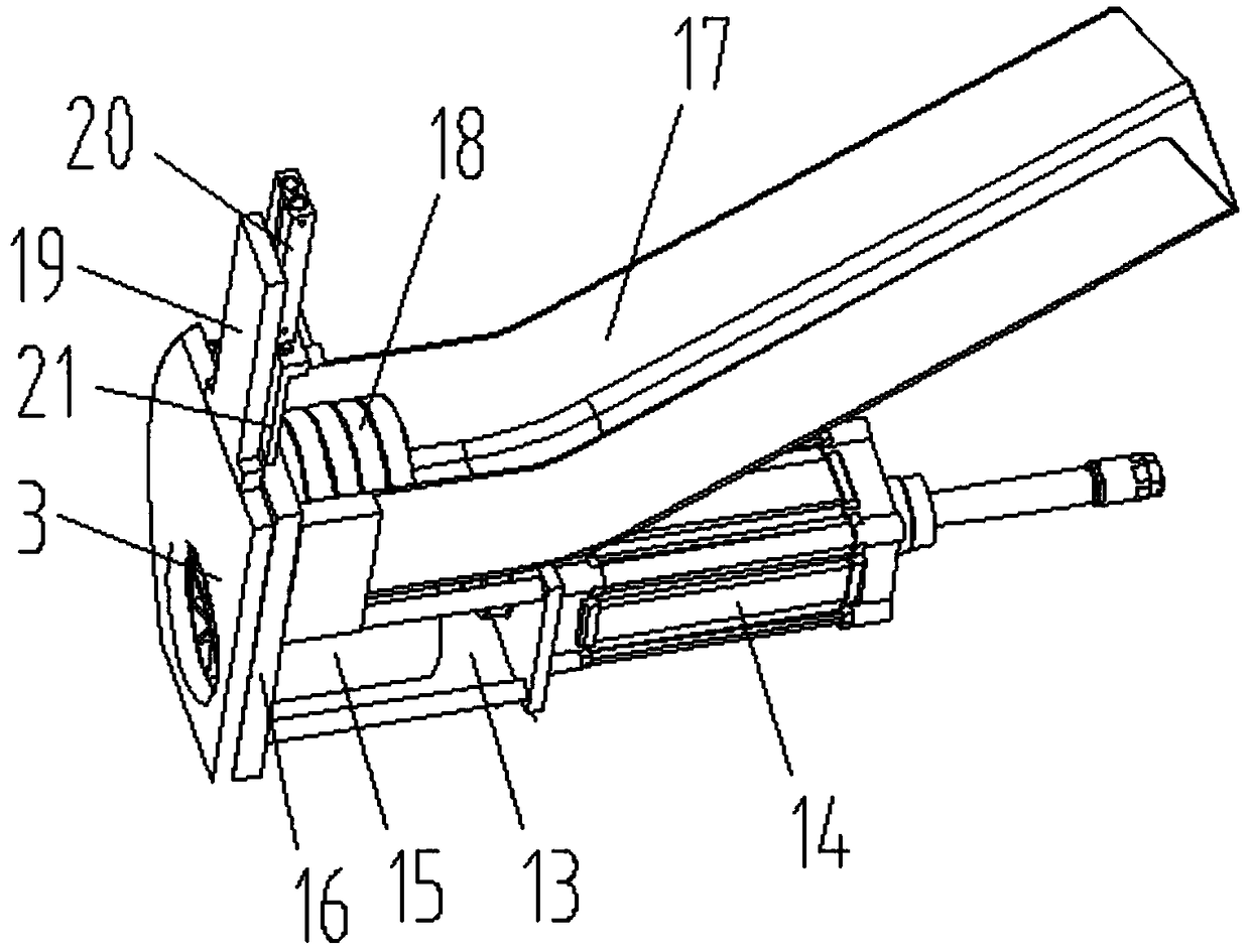
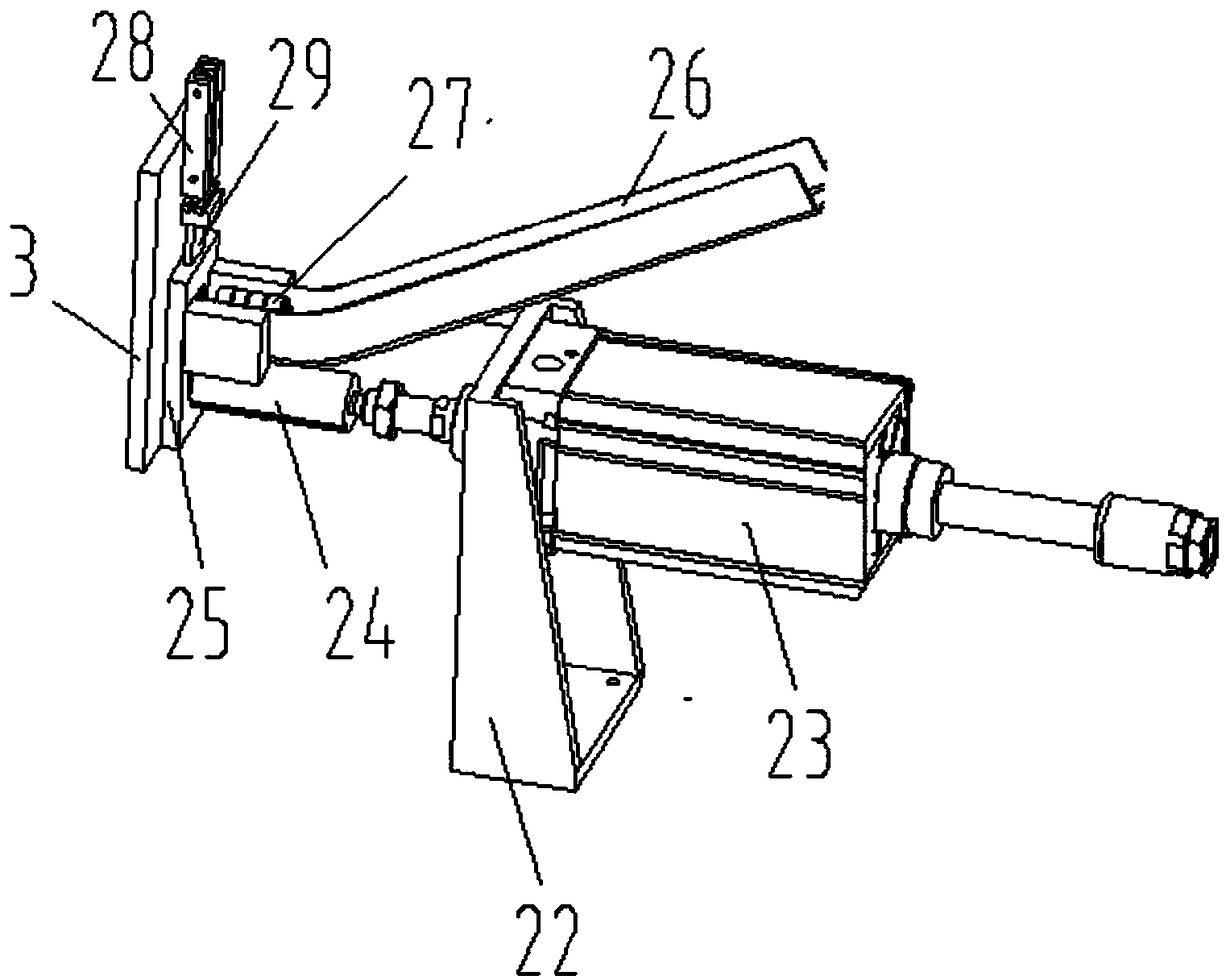
[0028] Such as Figure 1-Figure 4 As shown, the specific structure of the present invention is: a snap ring bearing fan blade automatic assembly machine for the rotor, which includes a power distribution control box 1 and an operation display screen 2 connected to each other, and the power distribution control box 1 is provided with A turntable frame 3, a vertical turntable 4 is installed on the turntable frame 3, and the drive motor of the turntable 4 is connected to the power distribution control box 1, and the turntable 4 is uniformly provided with mounting holes for matching with the rotor 12 , an...


PUM


Abstract

The present invention relates to an automatic assembly machine for a snap ring, a bearing and a fan blade of a rotor. The machine comprises a power distribution control box and an operation display panel which are connected to each other. The power distribution control box is provided with a turntable bracket on which a vertical turntable is arranged, and a drive motor of the turntable is connected to the power distribution control box. The turntable is evenly provided with mounting holes that match up with the rotor. Besides, on the power distribution control box on the side faces of the turntable, a fan blade assembly device, snap ring assembly devices and bearing assembly devices that match up with the rotor on the turntable are disposed in turn in the rotating direction of the turntable. The design of the present invention provides the vertical turntable that is connected to the power distribution control box and evenly provided with the mounting holes that match up with the rotor body. Besides, the fan blade assembly device, the snap ring assembly devices and the bearing assembly devices that match up with the rotor on the turntable are arranged on the side faces of the turntable so that integrated assembly of the fan blade, the snap ring and the bearing can be realized, assembly efficiency is greatly improved and production hours are reduced.

Description

technical field [0001] The invention relates to the field of rotor assembly equipment, in particular to an automatic assembly machine for rotor clasp bearing fan blades. Background technique [0002] The rotor is the core area of ​​the engine and electric motor. It generally includes the rotor coil and the rotor shaft. In the application field of the rotor, it is usually necessary to sleeve the fan blade at one end of the rotor shaft, and the snap ring and bearing at both ends. [0003] Most of the existing rotor snap rings, bearings and fan blades are assembled step by step. The assembly line is operated through multiple assembly equipment. The fan blades are first assembled by the fan blade assembly device, and then the rotor is taken out and put into the pressure ring. The snap ring is assembled at the bottom of the device, and then the rotor is taken out and put into the bearing assembly device for bearing assembly. During the whole process, the rotor needs to be picked ...

Claims


Application Information

Patent Timeline
Patent Type & Authority Patents(China)
IPC IPC(8): B23P19/027B23P19/00
CPCB23P19/001B23P19/004B23P19/027B23P21/002
Inventor 邓君黄红梅邓凯李培
Owner 馆陶县鑫荣轴承有限公司
Why Eureka
Eureka Blog
Learn More