
Laser cutting device for small-aperture pipelines

A laser cutting and small-diameter technology, which is applied in laser welding equipment, welding equipment, metal processing equipment, etc., can solve the problems that small-caliber pipe products cannot be processed, and achieve the effect of simple structure, smooth section and original shape

Inactive Publication Date: 2017-05-31
SUZHOU TIANHONG LASER
View PDF12 Cites 8 Cited by
  • Summary
  • Abstract
  • Description
  • Claims
  • Application Information

AI Technical Summary

Problems solved by technology

However, how to laser cut small-diameter pipes with a small buffer space is a bottleneck problem, and no major breakthrough has been made. In order to realize this breakthrough desire, several effective solutions have appeared on the market. Solution 1: small tube For the laser cutting scheme, see a patent of Foshan Hongshi Laser Technology Co., Ltd., application number CN201610773861.2, a small tube laser tube cutting machine and its cutting method, scheme two: laser cutting scheme for multi-angle cutting of pipes, see A patent of Guangzhou Tongrui Laser Equipment Co., Ltd., application number CN201510831101.8, laser pipe cutting machine and its pipe cutting method. These solutions have generally improved the efficiency of pipe processing and innovated pipe processing methods. However, these laser equipment are not The right is the cutting of conventional large-diameter pipes, but the problem of how to realize the fine processing of any pipe diameter in the range of 0.1-20mm has not been paid enough attention, resulting in the inability to complete the processing of small-diameter pipe products

Method used


Image

  • Laser cutting device for small-aperture pipelines

Examples


Embodiment

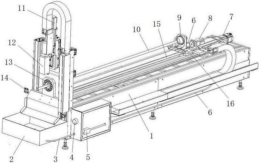
[0017] Such as figure 1 As shown, this embodiment provides a laser cutting device for small-diameter pipes, which includes a machine table; a pipe conveying mechanism is arranged above the machine for controlling the translation and rotation of the pipe; the pipe conveying mechanism A laser cutting mechanism is arranged above the left side; a receiving water tank 2 is arranged on the left side of the machine platform below the laser cutting mechanism; a water inlet pipe 3 is also arranged at the bottom of the material receiving water groove 2; the water inlet pipe 3 The other end of the water outlet is connected to the water inlet of the vacuum water pump 5 arranged on the front of the machine; the water outlet of the vacuum water pump 5 is connected to the water outlet pipe 6; the other end of the water outlet pipe 6 is connected to the right end of the pipe conveying mechanism for connecting The inner core of the right end of the pipe material 10; the position corresponding ...


PUM


Abstract

The invention relates to a laser cutting device for small-aperture pipelines. The laser cutting device for the small-aperture pipelines comprises a machine table, wherein a pipeline conveying mechanism is arranged above the machine table and used for controlling the translation and rotation of a pipeline; a laser cutting mechanism is arranged above the left side of the pipeline conveying mechanism; a material collecting water tank is arranged at the left side of the machine table and located below the laser cutting mechanism; the bottom of the material collecting water tank is provided with a water inlet pipe; the other end of the water inlet pipe is connected with a water inlet of a vacuum water pump arranged on the front of the machine table; a water outlet of the vacuum water pump is connected with a water outlet pipe; and the other end of the water outlet pipe is connected into the right end of the pipeline conveying mechanism and used for connecting an inner core at the right end of the pipeline. The laser cutting device for the small-aperture pipelines has the advantages that the precise machining of a product with any pipeline diameter in a region between 0.1mm and 20mm is realized, the kerf is neat, the fracture surface is smooth, high-temperature deformation produced during laser cutting is avoided, the initial shape of a machined material is ensured, the machining speed is raised, the structure is simple, and the manufacture cost is low.

Description

technical field [0001] The invention relates to the field of laser cutting of small-diameter pipes, in particular to a laser cutting device for small-diameter pipes. Background technique [0002] At present, laser pipe cutting technology has been widely used in pipe processing. With the rapid growth of my country's metal pipe production and consumption, China has developed into the world's largest steel production and consumption country. In recent years, in order to meet the needs of the industrial market, Various laser processing equipment products for cutting pipes and other three-dimensional workpieces have come out one after another and have been used in actual industrial production, especially in industries such as automobile manufacturing, oil exploration, machinery manufacturing, pipe processing and hardware accessories. The corresponding processing Process and technology research has also received more and more attention from the laser industry. With the diversified ...

Claims


Application Information

Patent Timeline
Patent Type & Authority Applications(China)
IPC IPC(8): B23K26/38B23K26/70
CPCB23K26/38B23K26/703
Inventor 金朝龙汪继影许立春李方超
Owner SUZHOU TIANHONG LASER
Learn More