Improved target furnace equipment and target bonding method

An improved target material technology, applied in welding equipment, metal processing equipment, metal processing, etc., can solve the problems of low sintering pass rate, high risk of later use, low melting point of indium, etc., and achieve simple manual operation procedures and bonding The effect of improving efficiency

Inactive Publication Date: 2017-05-31
QINGDAO BLUE LIGHT NEW MATERIAL CO LTD
View PDF10 Cites 3 Cited by
  • Summary
  • Abstract
  • Description
  • Claims
  • Application Information

AI Technical Summary

Problems solved by technology

However, due to the low melting point of indium, if the temperature is controlled too high during the manufacturing process, the liquid state of indium will flow out along the gap under pressure.
Therefore, how to solve the problem of low sintering pass rate and high risk of later use through temperature and pressure control is the core technology of the target bonding method

Method used


Image

  • Improved target furnace equipment and target bonding method

Examples


Embodiment 1

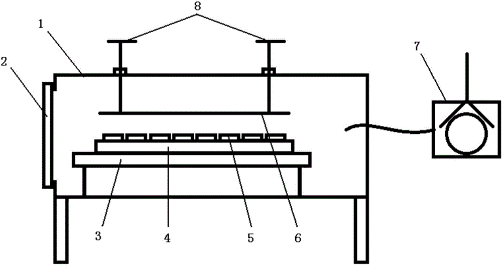
[0028] Such as figure 1 In the shown improved target furnace equipment, a furnace door 2 is set on one side of the furnace body 1, a heating base 3 is set inside the furnace body 1, and a heating device and a temperature detector for temperature control are installed inside the heating base 3 , the heating base 3 is bolted to the target substrate 4 for placing the target 5, and a stainless steel pressure plate 6 is arranged directly above the target substrate 4, and the length and width of the pressure plate 6 are not smaller than the target The length and width of the substrate 4, the upper end of the pressure plate 6 is connected to the manual pressure valve 8 outside the furnace body 1, there are two manual pressure valves 8, and the lower end of the manual pressure valve 8 is connected to the bottom of the pressure plate 6 respectively. At both ends, the interior of the furnace body 1 communicates with the external vacuum pump 7 .

Embodiment 2

[0030] A method for target bonding using the improved target furnace equipment described in Example 1: specifically comprising the following steps:

[0031] 1) First install a mold on the target substrate 4 and fix it;

[0032] 2) Place the indium balls in the mold and spread them evenly;

[0033] 3) The target material 5 is placed on the indium ball, and it is closely attached to the mold and fixed to ensure that no displacement occurs during the heating and pressing process;

[0034] 4) Use the manual pressure valve 8 to move down the pressure plate 6 to ensure that the pressure plate 6 and the target 5 are tightly locked, and close the furnace door 2;

[0035] 5) Turn on the vacuum pump 7 to pump the vacuum chamber of the equipment to 10Pa;

[0036] 6) Set the pressure value so that the pressure between the target substrate 4 and the target 5 is always maintained at about 2MPa; turn on the heating function to raise the temperature of the heating base 3 to 156°C;

[0037]...

Embodiment 3

[0040] The structure of each part of an improved target furnace equipment described in this embodiment is the same as that in Embodiment 1, and the different technical parameters are: the material of the pressure plate 6 is polytetrafluoroethylene.


PUM


Abstract

The invention discloses improved target furnace equipment, and belongs to the technical field of target bonding. A furnace door is arranged on one side of a furnace body of the improved target furnace equipment; the furnace body is internally provided with a heating base station; the heating base station is internally provided with a heating device and a temperature detector that are used for temperature control; a target substrate for the placement of a target is connected with the heating base station; a pressurization plate is arranged over the target substrate; the upper end of the pressurization plate is connected with a manual pressurization valve located outside the furnace body; and the interior of the furnace body communicates with an external vacuum pump. The improved target furnace equipment is simple in manual procedures and high in target bonding efficiency; through calculating a welded area and the mass of indium spheres, a situation that a utilization ratio of an indium material is above 98% can be guaranteed; air and water steam in the target and the target substrate can be reduced effectively through vacuumizing, and a situation that the welded area is above 97% can be guaranteed; and a yield of target bonding by a skilled worker can reach 100%.

Description

technical field [0001] The invention belongs to the technical field of target material bonding, and in particular relates to an improved target material furnace equipment and a target material bonding method. Background technique [0002] The bonding equipment of the target is composed of a heating belt and a pressurized screw, which can meet the needs of the market, but the process is relatively rough, and bonding pores are prone to appear, which will bring risks to the use of subsequent products. [0003] In addition, ordinary targets are required to be welded with indium balls to reduce manufacturing costs. However, due to the low melting point of indium, if the temperature is controlled too high during the manufacturing process, the liquid state of indium will flow out along the gap under pressure. Therefore, how to solve the problem of low sintering pass rate and high risk of later use through temperature and pressure control is the core technology of the target bondin...

Claims


Application Information

Patent Timeline
Patent Type & Authority Applications(China)
IPC IPC(8): B23K1/008B23K3/00
CPCB23K1/008B23K3/00
Inventor 张磊顾正张晓峰郭校亮陈良杰
Owner QINGDAO BLUE LIGHT NEW MATERIAL CO LTD
Why Eureka
Try Eureka