Spray boom assembly and lifting spraying device comprising same
A spray device and spray boom technology, which is applied in the field of spray machines, spray boom parts and their lifting spray devices, which can solve the problems of large turning radius, large horizontal space, and inability to ensure the passability of the walking chassis.
- Summary
- Abstract
- Description
- Claims
- Application Information
AI Technical Summary
Problems solved by technology
Method used
Image
Examples
Embodiment 1
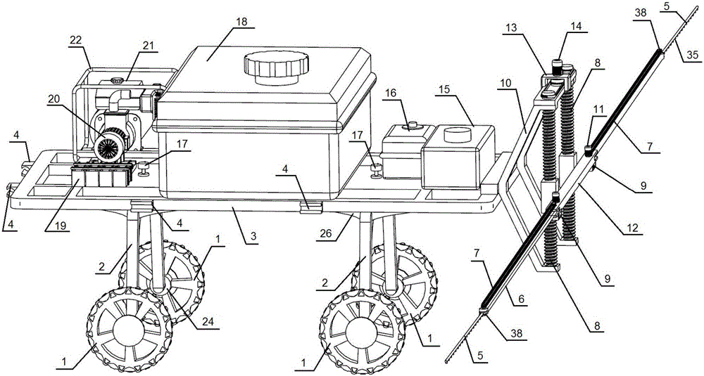
[0072] like Figure 5-6 As shown, the self-steering walking chassis includes a slewing mechanism and tires 1;
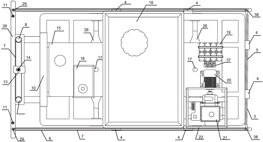
[0073] The car platform 3 is a metal frame welded by many square metal tubes and two square metal plates, which can effectively reduce the weight of the car platform. Many square metal tubes are welded into a 3×5 square space. Two square metal plates are fixed in the spaces of the second row and the fourth row, and spray rod placement grooves 4 are respectively welded on the front and left and right sides of the car platform 3, and 8 stoppers 23 are welded on the bottom of the car platform 3. The rear portion of the car platform 3 is reserved with a through hole 25 for the fixed central axis 27 to pass through;
[0074] Wheel 1 selects herringbone pattern agricultural tires for use, also can select other tires such as common non-pattern tires according to the demand of driving road surface, in-wheel motor 24 is housed in the wheel hub;
[0075] The slewing mechanis...
Embodiment 2
[0077] like Figure 7 As shown, the slewing mechanism includes a single-row tapered roller bearing 39, a support column 44, a shock absorber 47 and a shock-absorbing bracket 46, and the outer ring or inner ring of the single-row tapered roller bearing 39 is connected with the vehicle platform 3 by welding, and the single-row tapered roller bearing The inner ring or outer ring of the roller bearing 39 and the top surface of the support column 44 are fixed concentrically. There are three sets of shock absorbers 47, wherein one end of the shock absorber is respectively fixed on the symmetrical sides and below of the support column 44, and the other end is respectively Be fixed on both sides and the central position of the shock absorber 46, the shock absorber 46 is a high-strength square metal frame close to the width of the car, and the two ends of the shock absorber 46 are fixed with the fuselage of the hub motor 24.
Embodiment example 3
[0079] like Figure 8 As shown, the self-steering running mechanism includes a slewing mechanism and a tire 1 with a hub motor 24;
[0080] The slewing structure includes plane cylindrical bearing 42, chassis platform 26 and axle 2; The hole makes the cylindrical roller 40 of the plane cylindrical bearing 42 contact with the bottom of the car platform 3, and there is a circular groove in the middle of the chassis platform 26, and there are gradually shrinking extensions on the left and right sides of the chassis platform 26, and the plane of the plane cylindrical bearing 42 maintains The frame assembly and the circular groove of the chassis platform 26 are fixed concentrically. The axle 2 is made of metal. The top of the axle 2 is fixed to the extension of the chassis platform 26 and forms an obtuse angle with the chassis platform 26. The fuselage is fixed; because the height of the vehicle axle 2 is higher than the ground, so this embodiment is applicable to the working occa...
PUM
 Abstract
Description
Claims
Application Information
 - R&D
- Intellectual Property
- Life Sciences
- Materials
- Tech Scout
- Unparalleled Data Quality
- Higher Quality Content
- 60% Fewer Hallucinations
Browse by: Latest US Patents, China's latest patents, Technical Efficacy Thesaurus, Application Domain, Technology Topic, Popular Technical Reports.
© 2025 PatSnap. All rights reserved.Legal|Privacy policy|Modern Slavery Act Transparency Statement|Sitemap|About US| Contact US: help@patsnap.com


