Low-noise heat exchange equipment and heat exchange system
A technology of heat exchange equipment and heat exchange system, which is applied in the field of low-noise heat exchange equipment and heat exchange systems, can solve the problems of difficult replacement and high noise, and achieve the effects of easy replacement, reduced noise impact, and improved convenience of use
- Summary
- Abstract
- Description
- Claims
- Application Information
AI Technical Summary
Problems solved by technology
Method used
Image
Examples
Embodiment 1
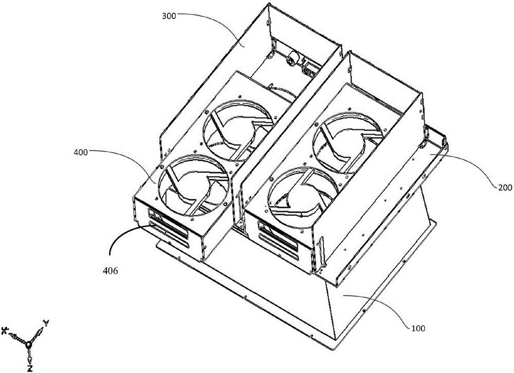
[0036] Embodiment 1 provides a kind of low-noise heat exchange equipment, such as figure 1 As shown, it includes a lower air channel 100 , a base plate 200 , a fan unit 400 and an upper air channel 300 , and the fan unit is detachably placed in the space formed by the base plate 200 and the upper air channel 300 .
[0037] The downflow channel 100 is located below the base plate 200 , and the hot air generated by the operation of the machine flows into the heat exchange device from the downflow channel 100 . Above the base plate 200 are the fan unit 400 and the upper air duct 300 , and the hot air flowing through the fan unit 400 flows out through the upper air duct 300 .
[0038]The upper air duct 300 is surrounded by three sides, and the three sides are the left side, the right side and the rear side respectively. The front of the upper air duct 300 is not provided with a closed surface, and the fan unit is assembled and disassembled through the front of the upper air duct....
Embodiment 2
[0046] Embodiment 2 provides a heat exchange system using the above heat exchange equipment, see Figure 5 , on the basis of the heat exchanging device, further comprising a rotational speed monitoring device signally connected to the heat exchanging device, and a rotational speed display unit connected to the rotational speed monitoring device. The rotational speed monitoring device is implemented based on a single-chip microcomputer.
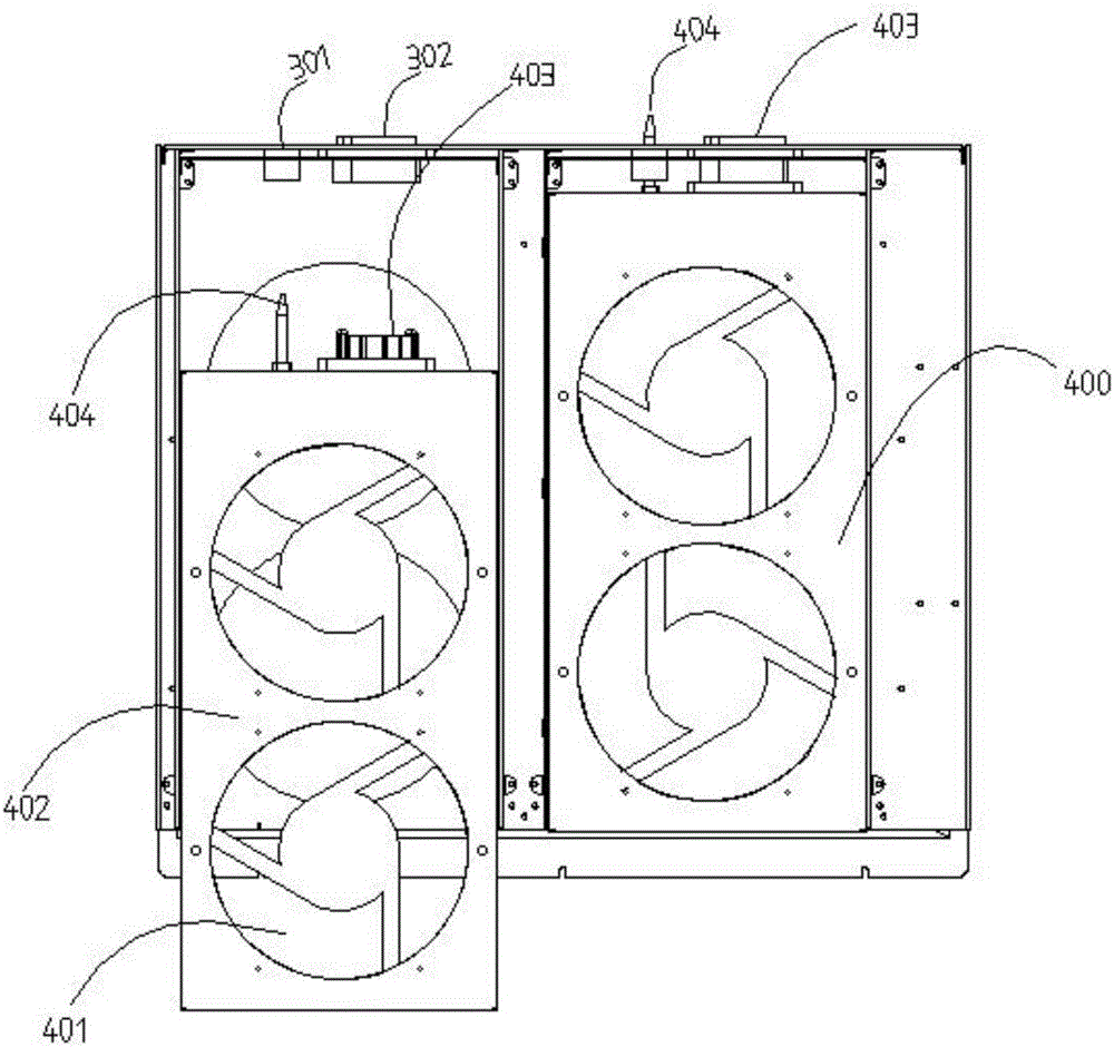
[0047] The heat exchange device is connected to a speed monitoring device for monitoring the speed of the fan through the fan plug 403 . The speed monitoring device is used to detect in real time whether the fan is working normally. Specifically, the fan 401 in the fan unit 400 is a three-wire DC fan. In addition to the common live wire and ground wire, the fan also has a speed monitoring wire. When the fan rotates a circle, the monitoring line outputs a square wave pulse. Within a predetermined time range, the rotational speed of the fan ...
Embodiment 3
[0050] Embodiment 3 provides a real-time monitoring method for heat exchange using the above-mentioned heat exchange system, see Image 6 , including the following steps:
[0051] S1, monitor the rotation of the fan through the speed monitoring line, the fan rotates one circle, and the speed monitoring line outputs a square wave pulse;
[0052] S2. The rotational speed monitoring device detects the number of square wave pulses within a predetermined time range, and judges the running condition of the fan accordingly.
[0053] S3, the speed monitoring device gives an alarm prompt to the faulty fan in the form of a buzzer alarm and / or uploading the speed information of the fan to the speed display unit.
[0054] When multiple fan units are connected, the speed monitoring device detects the speed of each fan separately, and if any fan is damaged, an alarm signal is sent immediately.
PUM
 Abstract
Description
Claims
Application Information
 - Generate Ideas
- Intellectual Property
- Life Sciences
- Materials
- Tech Scout
- Unparalleled Data Quality
- Higher Quality Content
- 60% Fewer Hallucinations
Browse by: Latest US Patents, China's latest patents, Technical Efficacy Thesaurus, Application Domain, Technology Topic, Popular Technical Reports.
© 2025 PatSnap. All rights reserved.Legal|Privacy policy|Modern Slavery Act Transparency Statement|Sitemap|About US| Contact US: help@patsnap.com


