
Programmable logic device, receiving card and led display control system

A technology of programming logic and receiving card, applied in the field of LED display control system, can solve the problems of image blurring effect, LED display cost increase, difficulty and complexity of LED display calibration link, etc., to improve compatibility, improve Display ability, the effect of improving the display effect

Active Publication Date: 2018-10-26
XIAN NOVASTAR TECH
View PDF7 Cites 0 Cited by
  • Summary
  • Abstract
  • Description
  • Claims
  • Application Information

AI Technical Summary

Problems solved by technology

However, due to the limitations of technology level, manufacturing process and cost, the large pixel pitch and low resolution have become the main obstacles restricting its development, which also makes it difficult for LED displays to achieve high resolution and clarity similar to LCD and PDP flat panel displays.
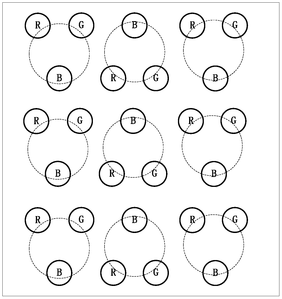
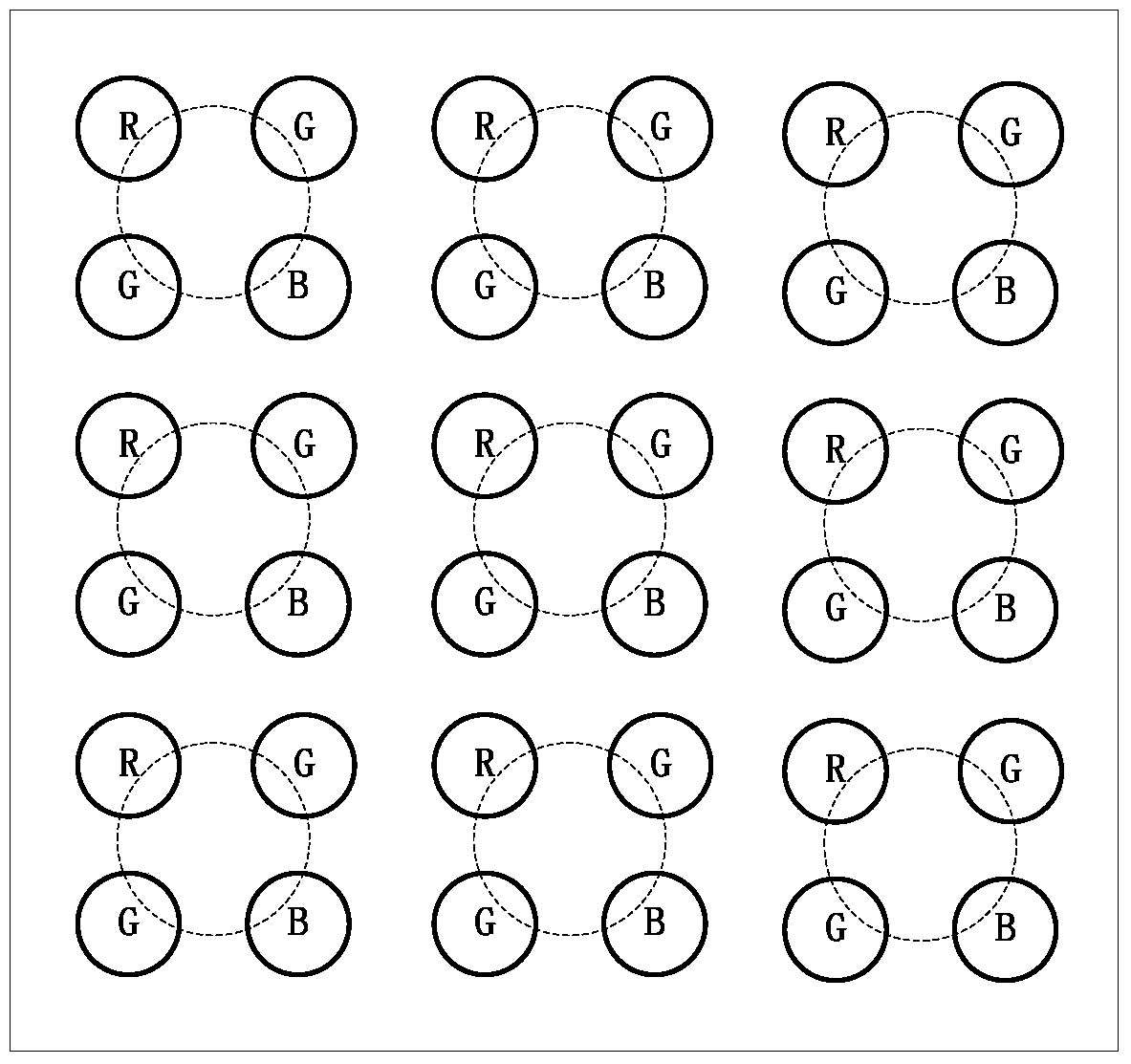
[0004] In order to realize high-resolution LED display, some schemes such as reducing the pitch of LED dot matrix and increasing the size of LED dot matrix have been proposed in the prior art. In addition, LED sub-pixel multiplexing technology has also been proposed in the existing technology. Taking the traditional RBGR mosaic arrangement (or diagonal arrangement) of LED display as an example, due to any Four adjacent sub-pixels can form a pixel, so this additional pixel between physical pixels is called a virtual pixel; for an LED display with a physical pixel resolution of M×N, the sub-pixel multiplexing technology can make The resolution of the LED display is increased by about 2 times in the horizontal and vertical directions, that is, it is expanded to (2M-1)×(2N-1)
Although the sub-pixel multiplexing technology increases the addressability of the system and improves the scale of the displayable image, the color value of each sub-pixel except the border is affected by 4 pixels, resulting in blurred images, thus Does not effectively improve image clarity

Method used


Image

  • Programmable logic device, receiving card and led display control system
  • Programmable logic device, receiving card and led display control system
  • Programmable logic device, receiving card and led display control system

Examples


Embodiment Construction

[0033] In order to make the above objects, features and advantages of the present invention more comprehensible, specific implementations of the present invention will be described in detail below in conjunction with the accompanying drawings.

[0034] The traditional receiving card usually receives the image data transmitted by the sending card through a network port such as a Gigabit network port, and then converts the network packet data into digital pixel data through an unpacking operation inside a programmable logic device such as an FPGA chip. The digital pixel data is subjected to operations such as Gamma transformation, correction, and data format conversion to obtain data suitable for LED light panel display, and finally drives the LED light panel for display through cable output.

[0035] The embodiment of the present invention applies the sub-pixel addressing and down-sampling technology to the process of image data processing by the receiving card, and preferably p...


PUM


Abstract

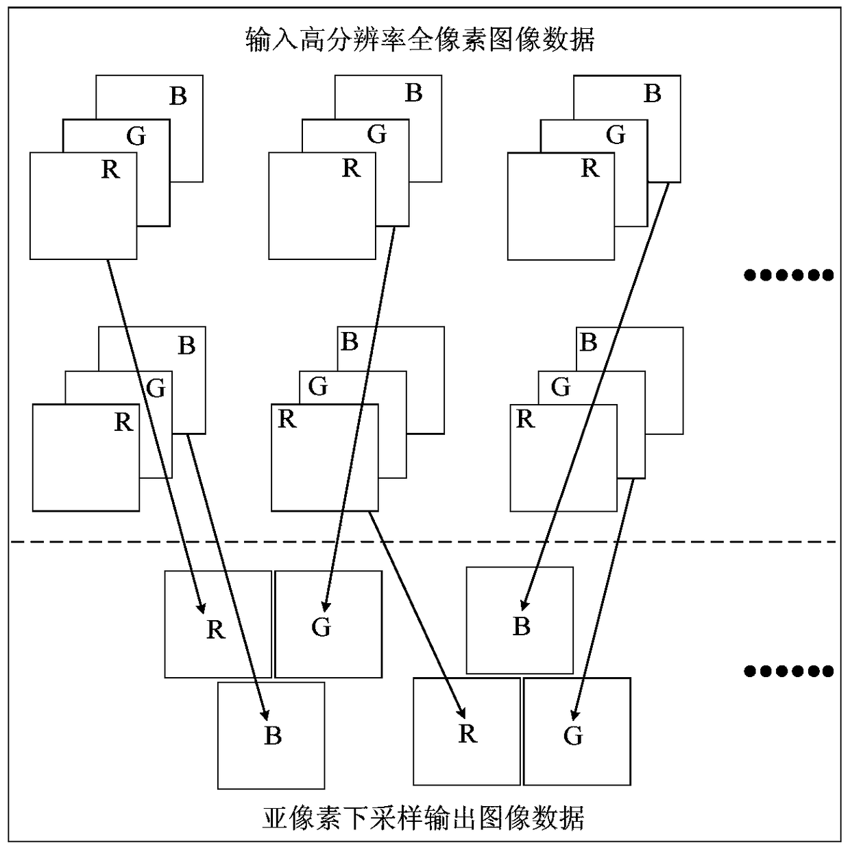
The invention relates to a programmable logic device, a receiving card and an LED display screen control system. The programmable logic device comprises a data unpacking module which is used for unpacking a data packet so as to output image data; a sub-pixel coding module which is used for performing sub-pixel addressing and down-sampling on the image data so as to obtain down-sampling image data; an input buffer module which is used for buffering the down-sampling image data; an RAM control module which is used for controlling the down-sampling image data to be written into the external RAM of the programmable logic device; a data processing module which is used for performing gamma processing on the down-sampling image data acquired from the external RAM through the RAM control module so as to obtain the down-sampling image data after gamma processing; and a display module which is used for performing data format conversion on the down-sampling image data after gamma processing and then outputting the data. Therefore, the high-definition and high-resolution frame can be displayed on an LED display screen of limited cost or relatively low physical resolution.

Description

technical field [0001] The invention relates to the technical field of image processing and display, in particular to a programmable logic device, a receiving card and an LED display control system. Background technique [0002] Most modern flat-panel displays use spatial methods to synthesize color, with each pixel on the display consisting of sub-pixels capable of producing three primary colors. When the sub-pixel pitch is small enough, color mixing occurs and various colors appear. The sub-pixels of the LED display correspond to light-emitting diodes of different primary colors (red, green, blue). Under the control of the driving signal, the three primary colors present various colors through color mixing and form an LED pixel. In the process of displaying images on the LED display, the pixel data of the video source can be completely mapped to the LED display one-to-one. [0003] Full-color LED display has almost occupied the entire field of indoor and outdoor large-sc...

Claims


Application Information

Patent Timeline
Patent Type & Authority Patents(China)
IPC IPC(8): G09G3/32
Inventor 袁胜春杨城滕鹏超
Owner XIAN NOVASTAR TECH
Learn More