
Boiler ash and slag removing system

A boiler ash removal and slag storage technology, applied in the field of mechanical processing, can solve the problem of unreasonable utilization of heat, etc., and achieve the effects of improving efficiency, reducing waste and enhancing use efficiency

Inactive Publication Date: 2017-05-24
JIASHAN YONGJIN METAL PROD
View PDF5 Cites 3 Cited by
  • Summary
  • Abstract
  • Description
  • Claims
  • Application Information

AI Technical Summary

Problems solved by technology

The furnace ash is taken away by the air supply required for boiler combustion due to its fine particle size, and then a separation device for flue gas and furnace ash is installed at the tail of the boiler flue for separation; however, commonly used boilers are either only for ash removal or are Separate slag removal, in the process of ash removal and slag removal, there is a high temperature in the bottom slag, and the commonly used boiler ash removal or slag removal system does not make reasonable use of these heat, so it is necessary to design a method that can make use of Waste heat becomes possible and can also be used in a system for both ash and slag removal

Method used


Image

  • Boiler ash and slag removing system
  • Boiler ash and slag removing system
  • Boiler ash and slag removing system

Examples


Embodiment Construction

[0019] In order to make the technical means, creative features, goals and effects achieved by the present invention easy to understand, the present invention will be further elaborated below in conjunction with illustrations and specific embodiments.

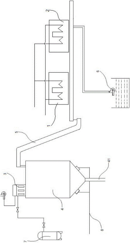
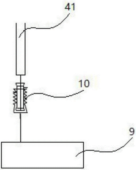
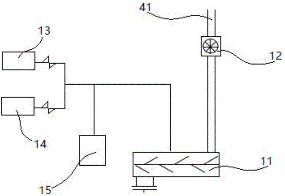
[0020] refer to figure 1 , figure 2 , image 3 As shown, the boiler ash removal system includes a cooling mechanism, a conveying mechanism and a processing mechanism. The cooling mechanism includes a slag cooler group, and the slag cooler group includes a first slag cooler 1 and a second cooler A slag container 2, the processing mechanism includes a dust collector 3 and a slag bin 4, the cooling mechanism and the processing mechanism are connected by a conveying mechanism 5, the slag cooler group is connected with a cooling pipe and a waste heat recovery pipe, and the cooling The pipes are respectively connected to the water inlet pipe of the first slag cooler 1 and the water outlet pipe of the second slag cooler 2, and the w...


PUM


Abstract

A boiler ash and slag removing system comprises a cooling mechanism, a conveying mechanism and a treatment mechanism. The cooling mechanism comprises a slag cooler set. The slag cooler set comprises a first slag cooler and a second slag cooler. The treatment mechanism comprises a dust collector and a slag bin. The cooling mechanism and the treatment mechanism are connected through the conveying mechanism. A chain conveyor is arranged at the bottom end of the slag cooler set. The slag outlet end of the first slag cooler and the slag outlet end of the second slag cooler are located at the upper end of the chain conveyor. Waste heat recycled by the slag coolers can be utilized, and waste is reduced. Through a sewage pump, fine dust in bottom slag conveyed on the chain conveyor can be removed, and the efficiency of the ash and slag removing system is improved. The slag bin can be connected with a wet ash and slag removing device or a dry coal ash removing device, the ash and slag removing efficiency is improved, the ash and slag removing manner is added, and the using efficiency of the system is improved.

Description

technical field [0001] The invention relates to the field of mechanical processing, in particular to a boiler ash removal system. Background technique [0002] With the development of science and technology, the field of mechanical processing is also developing rapidly. In mechanical processing and manufacturing, the use of boilers is indispensable. Common boilers need to be equipped with ash and slag removal devices. Ash and slag are both waste products after coal combustion. Whether it is a chain furnace, a pulverized coal furnace or a circulating fluidized bed boiler, it is the same. The slag is produced in the lower part of the boiler, and the particles are relatively coarse. It is generally divided into solid and liquid slag discharges. Basically, it is discharged continuously or periodically by gravity. Generally, it needs to be cooled with water when discharging, and the hot state discharge is generally at 800-1000 degrees, and the chain furnace is lower, and it is ge...

Claims


Application Information

Patent Timeline
Patent Type & Authority Applications(China)
IPC IPC(8): F23J1/06F27D15/02
CPCF23J1/06F27D15/02
Inventor 张玲玲
Owner JIASHAN YONGJIN METAL PROD
Learn More