Eureka AIR delivers breakthrough ideas for toughest innovation challenges, trusted by R&D personnel around the world.

Monitoring system and method of electromobile charging station

A technology of electric vehicles and monitoring systems, applied in the field of electric power, can solve the problems of low monitoring efficiency, achieve the effects of increasing monitoring functions, enhancing accuracy and timeliness, and solving low monitoring efficiency

Inactive Publication Date: 2017-05-24
STATE GRID BEIJING ELECTRIC POWER +1
View PDF5 Cites 6 Cited by
  • Summary
  • Abstract
  • Description
  • Claims
  • Application Information

AI Technical Summary

Problems solved by technology

[0004] Embodiments of the present invention provide a monitoring system and monitoring method for electric vehicle charging stations, to at least solve the technical problem of low monitoring efficiency of electric vehicle charging stations in the prior art

Method used

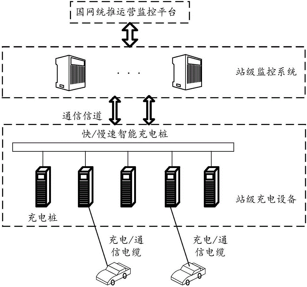
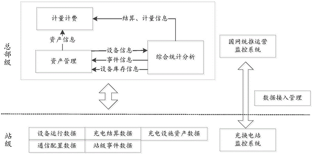

Image

  • Monitoring system and method of electromobile charging station
  • Monitoring system and method of electromobile charging station
  • Monitoring system and method of electromobile charging station

Examples


Embodiment 1

[0025] According to an embodiment of the present invention, an embodiment of a monitoring system for an electric vehicle charging station is provided. It should be noted that the steps shown in the flow chart of the accompanying drawings can be executed in a computer system such as a set of computer-executable instructions , and, although a logical order is shown in the flowcharts, in some cases the steps shown or described may be performed in an order different from that shown or described herein.

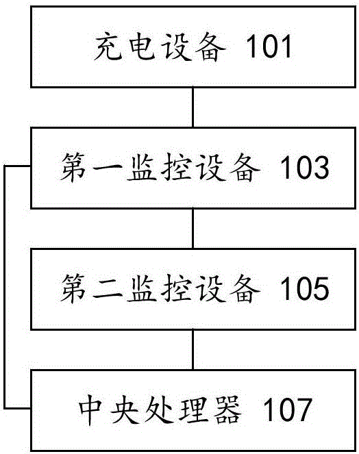
[0026] figure 1 is a schematic structural diagram of an optional monitoring system for an electric vehicle charging station according to an embodiment of the present invention, as shown in figure 1 As shown, the system includes:

[0027] The charging device 101 is used to charge the electric vehicle; the first monitoring device 103 is connected to the charging device 101 and is used to monitor the operating state of the charging device to obtain the first monitoring data; the sec...

Embodiment 2

[0063] According to another aspect of the embodiments of the present invention, an embodiment of a monitoring method for an electric vehicle charging station is also provided. It should be noted that the steps shown in the flow chart of the accompanying drawings can be executed in a set of computer-executable instructions such as and, although a logical order is shown in the flowcharts, in some cases the steps shown or described may be performed in an order different from that shown or described herein.

[0064] Figure 5 is a schematic flow chart of an optional monitoring method for an electric vehicle charging station according to an embodiment of the present invention, such as Figure 5 As shown, the method includes the following steps:

[0065] Step S502, monitoring the charging device according to the first monitoring device, so as to obtain the first monitoring data, wherein the first monitoring device is connected to the charging device, and the charging device is used...


PUM


Abstract

The invention discloses a monitoring system and method of an electromobile charging station. The monitoring system comprises charging equipment, first monitoring equipment, second monitoring equipment and a central processing unit. The charging equipment is used for charging an electromobile, the first monitoring equipment is connected with the charging equipment and used for monitoring running state of the same to acquire first monitoring data, the second monitoring equipment is connected with the first monitoring equipment and used for monitoring running state of the same to acquire second monitoring data, and the central processing unit is respectively connected with the first monitoring equipment and the second monitoring equipment and used for processing the first monitoring data and the second monitoring data to acquire control parameters which are used for remotely controlling the charging equipment. By the monitoring system and method, the technical problem of low monitoring efficiency of electromobile charging stations in the prior art is solved.

Description

technical field [0001] The invention relates to the field of electric power, in particular to a monitoring system and a monitoring method for an electric vehicle charging station. Background technique [0002] At present, the charging equipment of electric vehicles generally has the problem of being unable to provide cross-regional charging services, which brings inconvenience to the cross-regional travel of electric vehicle users. At present, a uniformly issued electric vehicle charging service card has been launched on the market to solve the problem of charging across regions. However, due to the different device models, device functions, and device control strategies of charging devices in each region, there is a lack of unified scheduling and management. The operation and maintenance enterprise of charging equipment cannot monitor and effectively manage multiple charging equipment in different regions in real time. Data conflicts occur frequently and transparency is poo...

Claims


Application Information

Patent Timeline
Patent Type & Authority Applications(China)
IPC IPC(8): B60L11/18G05B19/048H02J7/00
CPCH02J7/0027G05B19/048B60L53/31B60L53/665B60L53/68Y04S30/12Y02T10/7072Y02T10/70Y02T90/167Y02T90/16Y02T90/12
Inventor 孙舟王伟贤田贺平潘鸣宇李香龙
Owner STATE GRID BEIJING ELECTRIC POWER
Why Eureka
Eureka Blog
Learn More