Improved injection molding cooling system

A cooling system and injection molding machine technology, applied in the field of improved injection molding cooling system, can solve problems such as increasing production cost, shortening service life, and lowering work efficiency, and achieves the effects of reducing production cost, prolonging service life, and improving work efficiency

Inactive Publication Date: 2017-05-24
TIANJIN AODENA TECH
View PDF1 Cites 0 Cited by
  • Summary
  • Abstract
  • Description
  • Claims
  • Application Information

AI Technical Summary

Problems solved by technology

In order to ensure product quality, people have widely used injection molding cooling system to cool the mold after injection molding. At present, the existing injection molding cooling system can also cool down the injection molding machine, fixed mold and moving mold respectively, such as patent publication CN204295986U The disclosed system, but the sizes of the injection molding machine, the fixed mold, and the movable mold are inconsistent, and the flow rate of the required cooling water is also different. At the same time, the requirements for the flow rate are not the same. , the flow rate is also different. Although the system is equipped with a regulating valve, the flow and flow rate of the cooling water are adjusted through the regulating valve. The adjustment is not precise, and the flow rate and flow rate of the cooling water in the pipeline cannot be fully and accurately grasped. It may cause too much or too little flow of cooling water, which will not only lead to unsatisfactory cooling effect, but also may cause damage to the injection molding machine, fixed mold or moving mold, which reduces work efficiency, shortens service life, and improves the quality of life. production cost of the enterprise
[0003] In addition, most of the connected pipes of the system are airtight connections. If the pressure in the pipes is too high and not detected in time, it is very likely to cause serious production safety accidents, such as explosions, etc.

Method used


Image

  • Improved injection molding cooling system

Examples


Embodiment Construction

[0018] In order to further understand the content, characteristics and effects of the present invention, the following examples are given, and detailed descriptions are given below with reference to the accompanying drawings. It should be noted that this embodiment is descriptive, not restrictive, and cannot thereby limit the protection scope of the present invention.

[0019] The structural connections and working principles not specifically described in this patent application can be understood as prior art, such as the content disclosed in the patent publication CN204295986U.

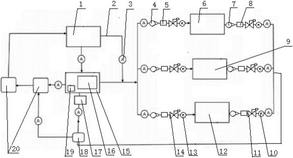
[0020] An improved cooling system for injection molding, such as figure 1 As shown, the system includes a cold water conveyor 1, a mold inlet and return water circulation device, a regulating valve 3, a water delivery pipe 2, a condenser 20 and an injection molding machine inlet and return water circulation device 6, and the mold inlet and return water circulation device includes a moving mold inlet ...


PUM


Abstract

The invention relates to an improved injection molding cooling system. The improved injection molding cooling system comprises a cold water conveyor, mould inflow and return water recycling devices, regulating valves, water pipes, condensers, and injection molding machine inflow and return water recycling devices; first flowmeters and first pitometers are uniformly arranged on the water pipes between water outlet ends of the cold water conveyor and the injection molding machine inflow and return water recycling devices, a movable die inflow and return water recycling device and a fixed die inflow and return water recycling device; second flowmeters and second pitometers are arranged at intervals on the water pipes among the injection molding machine inflow and return water recycling devices, the movable die inflow and return water recycling device, the fixed die inflow and return water recycling device. The improved injection molding cooling system is capable of providing users with flow speed and flow amount information of cooling water in pipes in time and accurately, ensuring cooling effect, avoiding damages of the injection molding machine, movable dies, and fixed dies, increasing working efficiency, prolonging equipment service life, and reducing production cost of enterprises.

Description

technical field [0001] The invention belongs to the technical field of injection molding equipment, in particular to an improved cooling system for injection molding. Background technique [0002] When the molten plastic fills the mold cavity under the pressure of the injection molding machine, it is necessary to wait until the plastic cools and solidifies to a certain hardness before opening the mold and ejecting the plastic part. Therefore, the temperature adjustment ability of the injection mold not only affects the quality of the plastic part, but also It also determines the production efficiency and is an important step in the injection molding work of the cooling operation mold. In order to ensure product quality, people have widely used injection molding cooling system to cool the mold after injection molding. At present, the existing injection molding cooling system can also cool down the injection molding machine, fixed mold and moving mold respectively, such as pat...

Claims


Application Information

Patent Timeline
Patent Type & Authority Applications(China)
IPC IPC(8): B29C45/72B29C45/73B29C45/78B29C45/84
CPCB29C45/72B29C45/73B29C45/78B29C45/84B29C2945/76531
Inventor 滑鹏高
Owner TIANJIN AODENA TECH
Why Eureka
Try Eureka