
Linear cutting slope oscillating bar wire arraying mechanism and linear cutting machine tool

A wire cutting slope and wire cutting technology, applied in metal processing equipment, manufacturing tools, electric processing equipment, etc., can solve the problems of single working mode, the angle of the working section of the electrode wire cannot be changed and adjusted, etc., to achieve the effect of convenient cutting and processing

Inactive Publication Date: 2017-05-24
SANGUANG ELECTRIC WORKING SUZHOU
View PDF8 Cites 0 Cited by
  • Summary
  • Abstract
  • Description
  • Claims
  • Application Information

AI Technical Summary

Problems solved by technology

[0003] Most of the wire electrode working sections of existing wire cutting machine tools are arranged horizontally or vertically, and the angle of the electrode wire working section cannot be changed to adapt to the cutting angle during cutting, and the work can only be completed by adjusting the position and angle of the workpiece to be cut. , the way of working is too single

Method used


Image

  • Linear cutting slope oscillating bar wire arraying mechanism and linear cutting machine tool
  • Linear cutting slope oscillating bar wire arraying mechanism and linear cutting machine tool

Examples


Embodiment Construction

[0029] The above solution will be further described below in conjunction with specific embodiments. It should be understood that these examples are used to illustrate the present invention and not to limit the scope of the present invention. The implementation conditions used in the examples can be further adjusted according to the conditions of specific manufacturers, and the implementation conditions not indicated are usually the conditions in routine experiments.

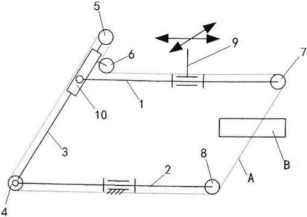
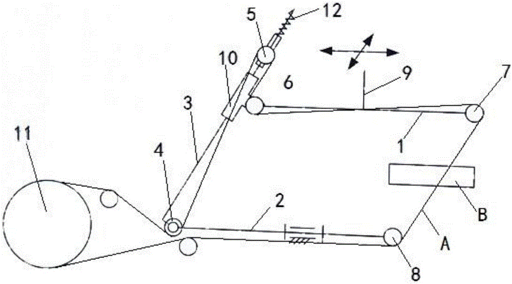
[0030] figure 2 It shows a specific embodiment of the application of the wire-cutting slope swing rod wire-discharging mechanism of the present invention on a wire-cutting machine tool. The mechanism mainly includes a base frame (not shown in the figure), an upper arm 1, a lower arm 2, and a sliding sleeve 10, pendulum bar 3, the first row of silk wheels 4, the second row of silk wheels 5, the third row of silk wheels 6, the fourth row of silk wheels 7 and the fifth row of silk wheels 8. in:

[0031] In actua...


PUM


Abstract

The invention discloses a linear cutting slope oscillating bar wire arraying mechanism. The linear cutting slope oscillating bar wire arraying mechanism comprises a bed frame, an upper arm, a lower arm, a sliding sleeve hinged to the upper arm, an oscillating bar, a first wire arraying wheel, a second wire arraying wheel, a third wire arraying wheel, a fourth wire arraying wheel and a fifth wire arraying wheel, wherein the upper arm can move along the X axis and the Y axis, the length of the upper arm is increased along the X axis, the lower arm is arranged parallel to the upper arm and can do pivot movement around the axis of the lower arm, and the oscillating bar penetrates the sliding sleeve in an axial and slideable manner and is hinged to the lower arm; the first wire arraying wheel is arranged at the hinged position between the oscillating bar and the lower arm in a pivoted manner; the second wire arraying wheel and the third wire arraying wheel are connected to the oscillating bar in a pivoted manner; the fourth wire arraying wheel is connected to the upper arm in a pivoted manner, the fifth wire arraying wheel is connected to the lower arm in a pivoted manner; the hinged point between the oscillating bar and the lower arm, the hinged point between the sliding sleeve and the upper arm, the fourth wire arraying wheel and the fifth wire arraying wheel are distributed on the four vertexes of a parallelogram. When the linear cutting slope oscillating bar wire arraying mechanism is used for carrying out cutting treatment on a workpiece, the cutting angles of the working segment of an electrode wire in two specific directions can be adjusted at will, and the tension of the electrode wire cannot be changed.

Description

technical field [0001] The invention relates to the field of wire cutting machine tools, in particular to a transverse cutting wire cutting machine tool. Background technique [0002] The working principle of the wire cutting machine tool is: the electrode wire wound on the wire reel moves at a certain speed along the rotation direction of the wire reel, and the workpiece installed on the machine tool table is made by the table according to the predetermined control trajectory relative to the electrode wire. During the forming movement, one pole of the pulse power supply is connected to the workpiece, and the other pole is connected to the electrode wire. A certain discharge gap is always maintained between the workpiece and the electrode wire and the working fluid is sprayed. The spark discharge between the electrodes corrodes a certain gap. Continuous Continuous pulse discharge cuts out workpieces of required shape and size. [0003] Most of the wire electrode working sec...

Claims


Application Information

Patent Timeline
Patent Type & Authority Applications(China)
IPC IPC(8): B23H7/08
CPCB23H7/105
Inventor 吕大伟李杰
Owner SANGUANG ELECTRIC WORKING SUZHOU
Learn More