Eureka AIR delivers breakthrough ideas for toughest innovation challenges, trusted by R&D personnel around the world.

Chemical material stirring and mixing equipment with high stirring force

A technology of mixing and stirring force, which is applied in the field of mixing and mixing equipment for chemical materials, can solve the problems of mixing tanks prone to mixing dead angle, unreasonable structure design, insufficient mixing, etc., and achieves benefits of mixing and mixing, increased spraying speed, and high-efficiency mixing mixed effect

Inactive Publication Date: 2017-05-24
郑州吉音动漫科技有限公司
View PDF0 Cites 5 Cited by
  • Summary
  • Abstract
  • Description
  • Claims
  • Application Information

AI Technical Summary

Problems solved by technology

[0002] At present, with the development of science and technology, the fields of industry and coal mining are developing at a high speed. In these fields, it is often necessary to stir some materials for later processing. Some chemical raw materials often need to add other chemical raw materials. The raw materials can be fully mixed with other raw materials, but the existing stirring device is not only insufficient due to its unreasonable structural design, but also there are easy to stir dead angles inside the stirring tank, resulting in low stirring efficiency and poor mixing quality

Method used


Image

  • Chemical material stirring and mixing equipment with high stirring force
  • Chemical material stirring and mixing equipment with high stirring force
  • Chemical material stirring and mixing equipment with high stirring force

Examples


Embodiment Construction

[0022] The technical solution of this patent will be further described in detail below in conjunction with specific embodiments.

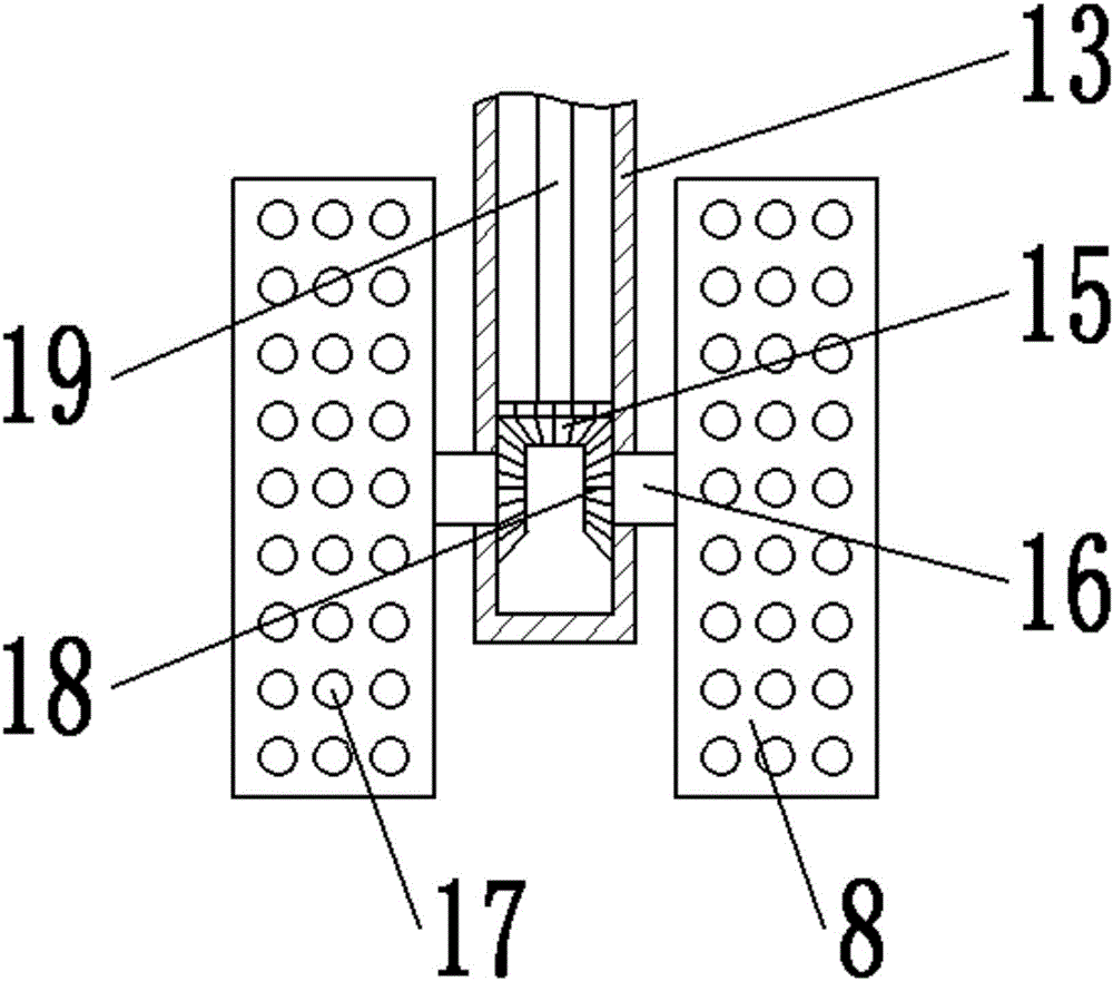
[0023] see Figure 1-7 , a chemical material mixing equipment with high stirring force, including a tank body 7 and an upper cover 2; the tank body 7 is set as a hollow cylinder made of stainless steel, and the inside is set as a stirring chamber 12, and the top opening is provided with The upper cover 2; the upper cover 2 is fixedly connected with the tank body 7 through the mutual screwing of the bolts 6 and the nuts 5; A liquid inlet device 14 is provided on the surface; a transmission device 3 is provided in the rotating disk mounting groove 37; the transmission device 3 is composed of a first motor 21 and a first spur gear 22; The upper cover 2 is fixedly connected, and the main shaft of the first motor 21 is fixedly connected with the first spur gear 22; the transmission device 3 is composed of a turntable 25, a second spur gear 24, a second...


PUM


Abstract

The invention provides chemical material stirring and mixing equipment with high stirring force. The chemical material stirring and mixing equipment comprises a tank body and an upper lid; the inside of the tank body is provided with a stirring cavity; the upper surface of the upper lid is provided with a driving device and a transmission device, and the lower surface of the upper lid is provided with a liquid entering device; the transmission device is arranged in a turntable mounting groove; the transmission device is composed of a first motor and a first straight gear; the transmission device is composed of a turntable, a second straight gear, a second gear and a sleeve; the liquid entering device is composed of a spraying dish and a liquid entering pipe; the bottom of the stirring cavity is provided with a stirring device; the stirring device is composed of a third motor, a stirring shaft and a stirring plate. According to the chemical material stirring and mixing equipment with the high stirring force, the driving device and the transmission device drive a stirring piece to conduct the rotation in the horizontal direction and the rotation in the vertical direction, which is beneficial to conducting efficient stirring on materials in the tank body; the spraying area and the spraying speed of liquid materials are increased through the liquid entering device, which brings convenience to sufficient contact with solid materials, and is beneficial to fast stirring and mixing among the materials.

Description

technical field [0001] The invention relates to chemical equipment, in particular to a chemical material mixing equipment with high stirring force. Background technique [0002] At present, with the development of science and technology, the fields of industry and coal mining are developing at a high speed. In these fields, it is often necessary to stir some materials for later processing. Some chemical raw materials often need to add other chemical raw materials. The raw materials are fully mixed with other raw materials, but the existing stirring device is not only insufficient due to its unreasonable structural design, but also there are easy to stir dead angles inside the stirring tank, resulting in low stirring efficiency and poor mixing quality. Contents of the invention [0003] The object of the present invention is to provide a chemical material stirring and mixing equipment with high stirring force, so as to solve the problems raised in the above-mentioned backgr...

Claims


Application Information

Patent Timeline
IPC IPC(8): B01F7/16B01F15/02
CPCB01F27/11251B01F27/808B01F27/191B01F27/85B01F35/712B01F35/7179
Inventor 不公告发明人
Owner 郑州吉音动漫科技有限公司
Why Eureka
Eureka Blog
Learn More