Fault processing method, network device and system
A fault handling method and network equipment technology, applied in the field of network management, can solve problems such as network oscillation and lower network reliability
- Summary
- Abstract
- Description
- Claims
- Application Information
AI Technical Summary
Problems solved by technology
Method used
Image
Examples
Embodiment 1
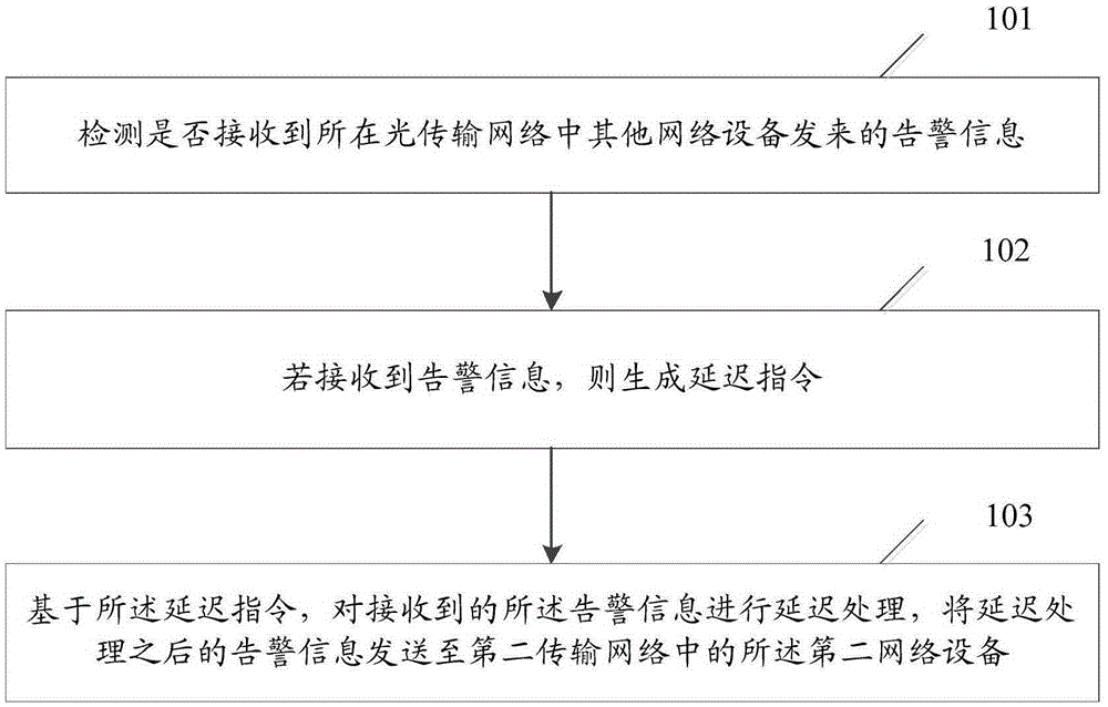
[0034] An embodiment of the present invention provides a fault handling method, which is applied to a first network device. The network device is set to be connected to the first transmission network and to the second network device in the second transmission network. The first transmission network Different from the second transmission network, such as figure 1 As shown, the method includes:
[0035] Step 101: Detect whether the alarm information sent by other network devices in the optical transmission network is received;
[0036] Step 102: If the alarm information is received, generate a delay instruction;
[0037] Step 103: Based on the delay instruction, perform delayed processing on the received alarm information, and send the delayed alarm information to the second network device in the second transmission network.
[0038] In this embodiment, the first transmission network may be an optical transmission network, and the second transmission network may be an Internet...
Embodiment 2
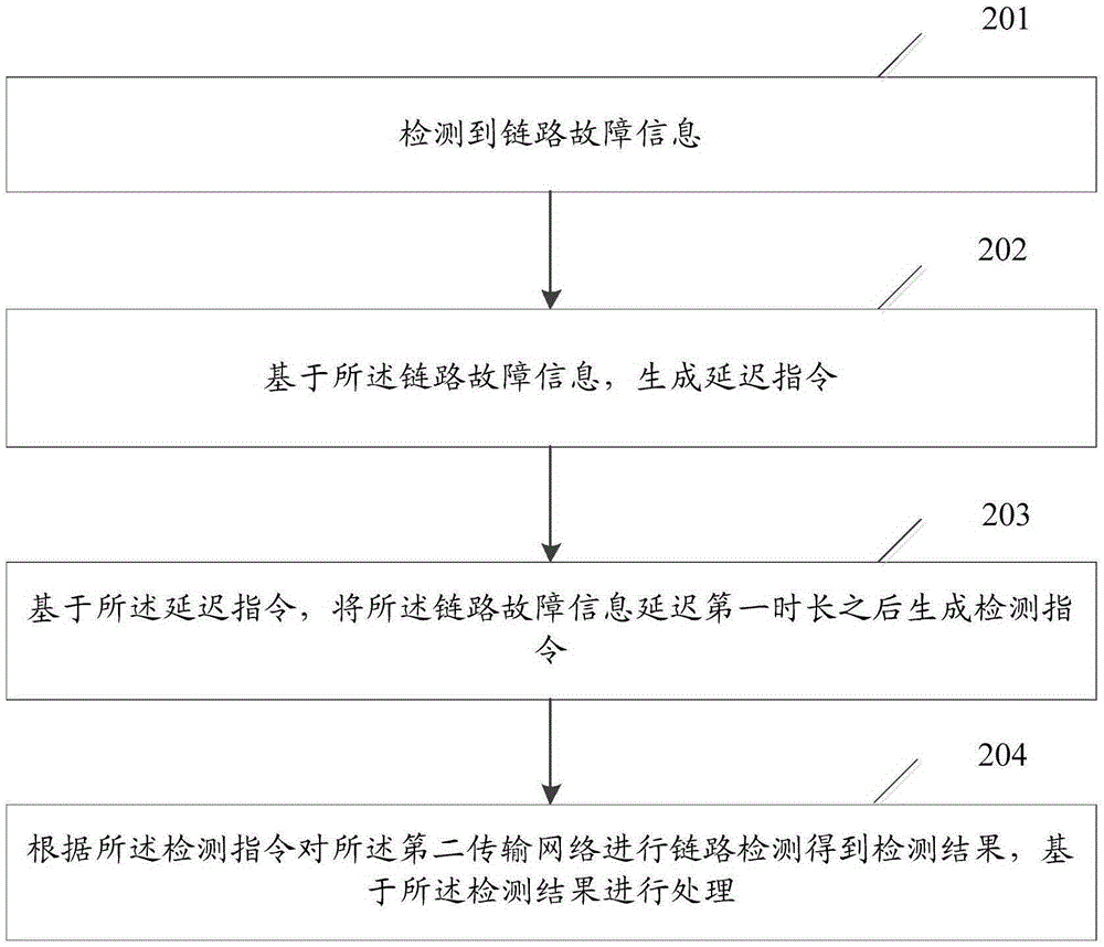
[0050] An embodiment of the present invention provides a fault handling method, which is applied to a second network device, and the second network device is set in a second transmission network, such as figure 2 As shown, the method includes:
[0051] Step 201: link failure information is detected;
[0052]Step 202: Generate a delay instruction based on the link failure information;
[0053] Step 203: Based on the delay instruction, generate a detection instruction after delaying the link failure information for a first period of time;
[0054] Step 204: Perform link detection on the second transmission network according to the detection instruction to obtain a detection result, and perform processing based on the detection result.
[0055] Preferably, before executing step 202 to generate the delay instruction, it may further include: detecting whether the link is restored to normal, and obtaining a first detection result; if the first detection result indicates that the ...
Embodiment 3
[0062] An embodiment of the present invention provides a network device, the network device is set on a first transmission network and connected to a second network device in a second transmission network, the first transmission network is different from the second transmission network ,Such as image 3 As shown, the network equipment includes:
[0063] The first receiving unit 31 is used to detect whether the alarm information sent by other network equipment in the optical transmission network is received;
[0064] The first processing unit 32 is configured to generate a delay instruction if the warning information is received;
[0065] The first sending unit 33 is configured to perform delayed processing on the received alarm information based on the delay instruction, and send the delayed processed alarm information to the second network device in the second transmission network.
[0066] In this embodiment, the first transmission network may be an optical transmission ne...
PUM
 Abstract
Description
Claims
Application Information
 - R&D
- Intellectual Property
- Life Sciences
- Materials
- Tech Scout
- Unparalleled Data Quality
- Higher Quality Content
- 60% Fewer Hallucinations
Browse by: Latest US Patents, China's latest patents, Technical Efficacy Thesaurus, Application Domain, Technology Topic, Popular Technical Reports.
© 2025 PatSnap. All rights reserved.Legal|Privacy policy|Modern Slavery Act Transparency Statement|Sitemap|About US| Contact US: help@patsnap.com


