Overhead line entanglement removing apparatus
A technology for overhead lines and clearing devices, applied in the direction of overhead lines/cable equipment, etc., can solve the problems of laborious and time-consuming clearing, poor working reliability, poor effect, etc.
- Summary
- Abstract
- Description
- Claims
- Application Information
AI Technical Summary
Problems solved by technology
Method used
Image
Examples
Embodiment 1
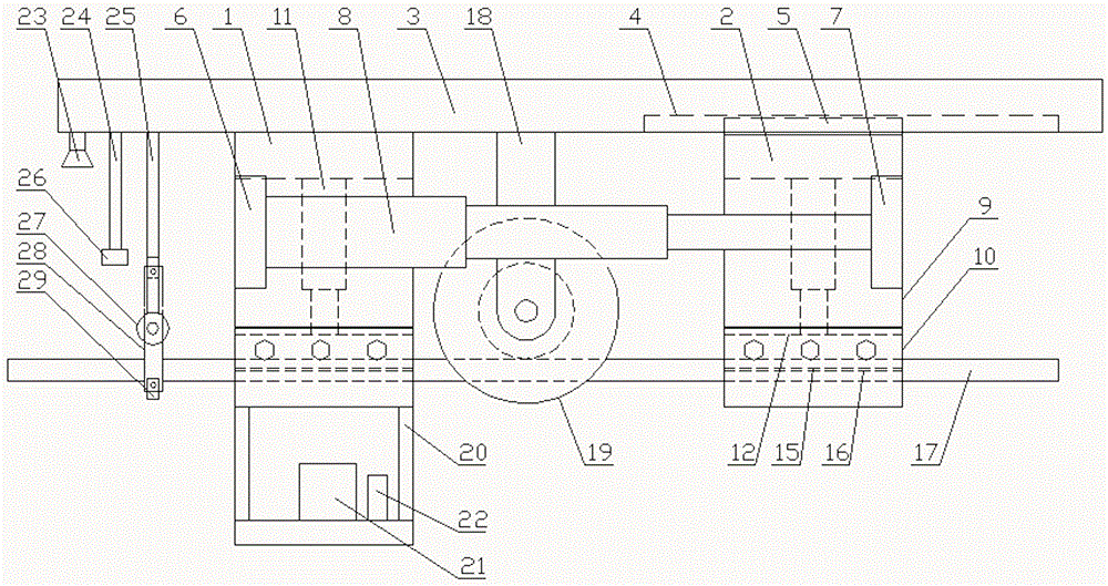
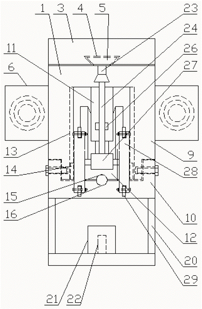
[0038] Such as figure 1 with figure 2 As shown, a device for removing entanglements of overhead lines includes a traveling mechanism and a clearing mechanism arranged on the traveling mechanism. The traveling mechanism includes a left traveling frame 1 and a right traveling frame 2. A crossbeam 3, the bottom surface of the crossbeam 3 is provided with a first dovetail groove 4, and the top of the right walking bracket 2 is provided with a first dovetail tenon 5 matched with the first dovetail groove 4;
[0039] Base 6 is all set on the front and rear sides of described left walking support 1, and push plate 7 is all set on the front and rear sides of described right walking support 2, and the first automatic telescoping link 8 is set on described base 6, and described first automatic The free end of telescoping rod 8 is arranged on described push plate 7;
[0040] The structure of the left walking support 1 and the right walking support 2 are the same and both include an up...
Embodiment 2
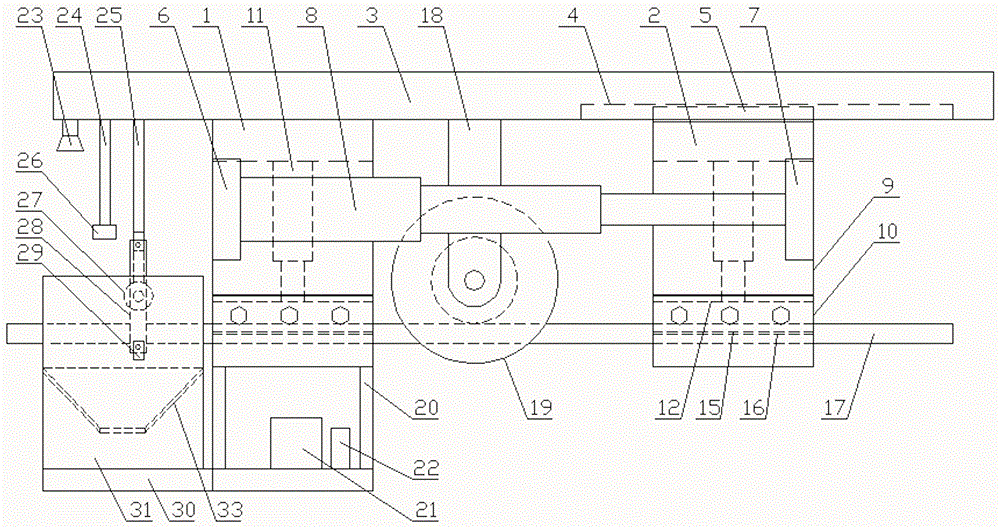
[0054] Such as image 3 with Figure 4 As shown, a device for removing entanglements of overhead lines includes a traveling mechanism and a clearing mechanism arranged on the traveling mechanism. The traveling mechanism includes a left traveling frame 1 and a right traveling frame 2. A crossbeam 3, the bottom surface of the crossbeam 3 is provided with a first dovetail groove 4, and the top of the right walking bracket 2 is provided with a first dovetail tenon 5 matched with the first dovetail groove 4;
[0055] Base 6 is all set on the front and rear sides of described left walking support 1, and push plate 7 is all set on the front and rear sides of described right walking support 2, and the first automatic telescoping link 8 is set on described base 6, and described first automatic The free end of telescoping rod 8 is arranged on described push plate 7;
[0056] The structure of the left walking support 1 and the right walking support 2 are the same and both include an up...
Embodiment 3
[0068] Such as Figure 5 with Image 6 As shown, the difference between it and Embodiment 2 is that: the front and rear sides of the bottom of the bearing bracket 20 are provided with traction plates 34, and the traction plates 34 are provided with traction holes 35, and traction ropes 36 are arranged in the traction holes 35.
[0069] An anchor rod or an anchor is arranged at the lower end of the traction rope 36 .
[0070] In this embodiment, traction plates are provided on the front and rear sides of the bottom of the bearing bracket, and traction holes are provided on the traction plates to facilitate fixing the traction rope on the traction plate, so that ground personnel can prevent the device from galloping during work through the traction rope. Anchor rods are arranged at the lower end of the traction rope so that the device is temporarily fixed on the ground by the traction rope. Obviously, an anchor is set at the lower end of the traction rope and can also have the ...
PUM
 Abstract
Description
Claims
Application Information
 - R&D Engineer
- R&D Manager
- IP Professional
- Industry Leading Data Capabilities
- Powerful AI technology
- Patent DNA Extraction
Browse by: Latest US Patents, China's latest patents, Technical Efficacy Thesaurus, Application Domain, Technology Topic, Popular Technical Reports.
© 2024 PatSnap. All rights reserved.Legal|Privacy policy|Modern Slavery Act Transparency Statement|Sitemap|About US| Contact US: help@patsnap.com


