
Method and equipment for leaking radiation testing of radiation source components

A technology of testing equipment and a testing method, which is applied in the field of radiation leakage testing of radiation source components, can solve problems such as high equipment procurement costs and high maintenance costs, and achieve the effects of taking into account both testing accuracy and testing efficiency, reducing costs, and simplifying testing equipment

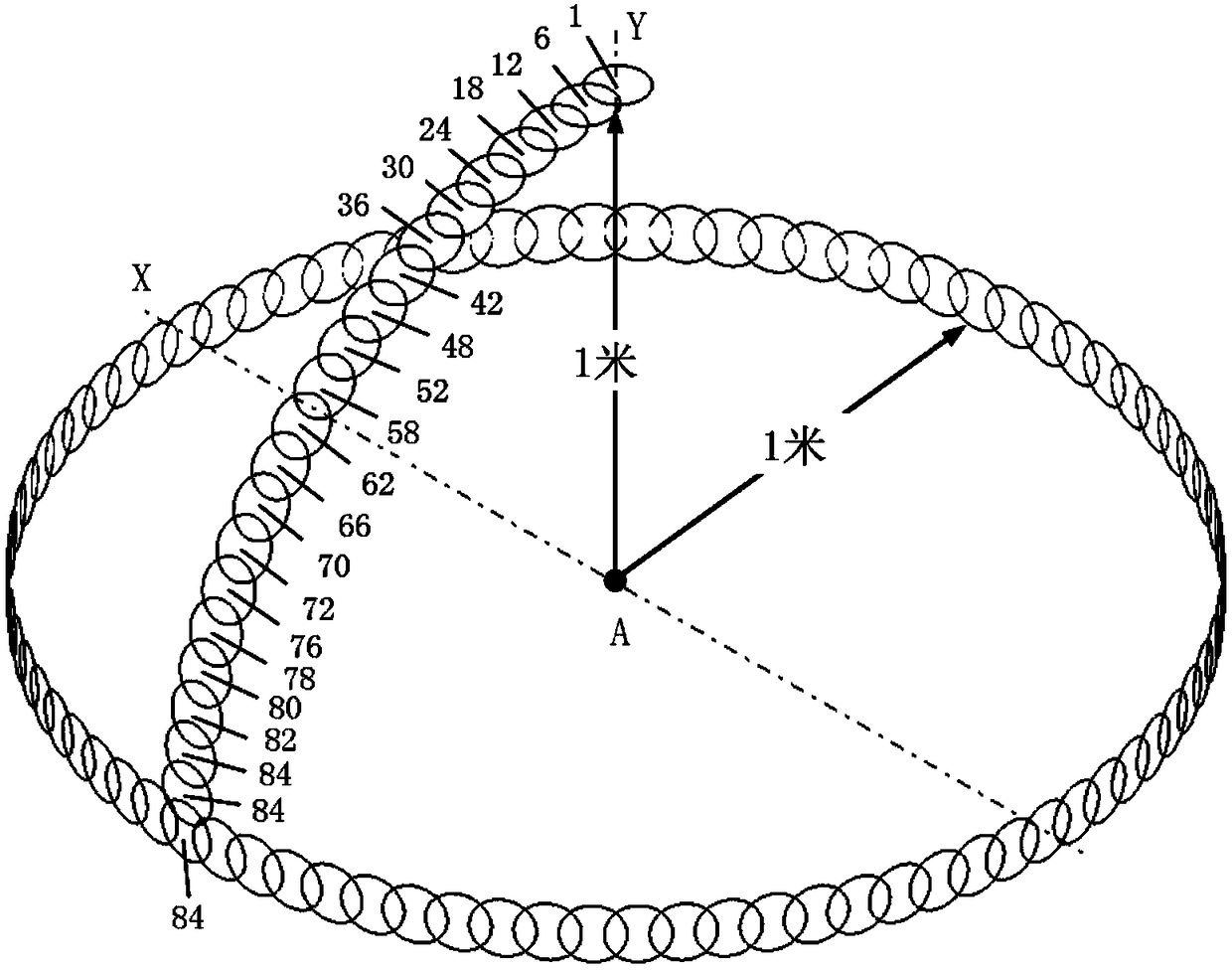
Active Publication Date: 2018-11-06
NEUSOFT MEDICAL SYST CO LTD
View PDF5 Cites 0 Cited by
  • Summary
  • Abstract
  • Description
  • Claims
  • Application Information

AI Technical Summary

Problems solved by technology

[0006] It can be seen that there are 18 measuring probes in the existing technology, and all the probes need to be calibrated every three months. The purchase cost of the equipment and the later maintenance cost are relatively high.

Method used


Image

  • Method and equipment for leaking radiation testing of radiation source components
  • Method and equipment for leaking radiation testing of radiation source components
  • Method and equipment for leaking radiation testing of radiation source components

Examples


Embodiment 1

[0099] like Figure 4 As shown, in a specific embodiment, the first swing arm 2 can be L-shaped, its horizontal part is used to be hinged with the mounting base 4, and the vertical part is hinged with the second swing arm 3, and the first swing arm 2 The vertical part can be arranged perpendicular to the rotary shaft of the second rotary arm 3. At this time, the rotary shaft of the first rotary arm 2 is in a direction parallel to the vertical part.

[0100] In detail, this embodiment is also provided with a column 9 and a supporting plate 10, the central axis of the column 9 coincides with the axis of rotation of the first rotary arm 2, and the lower end of the column 9 is hinged with the transverse part of the first rotary arm 2. At this time, the column 9 is used as the rotating shaft of the first rotating arm 2; the upper end of the column 9 is provided with a supporting plate 10, and the mounting seat 4 is detachably arranged on the supporting plate 10. Through this struc...

Embodiment 2

[0120] like Figure 5 As shown, in another specific embodiment, the first slewing arm 2 can be in the form of a broken line, including a first arm 21 and a second arm 22 connected to each other, wherein the first arm 21 extends from top to bottom, and the second arm 21 extends from top to bottom. The arm 22 is bent from the lower end of the first arm 21 towards the focal point A of the radiation source in the radiation source assembly, the upper end of the first arm 21 is hinged to the second rotating arm 3, and the second arm 22 is connected with a rotating shaft 23 extending up and down as the first The rotating shaft of a rotating arm 2, that is to say, the rotating shaft 23 can rotate relative to the mounting seat 4, so as to realize the rotation of the first rotating arm 2 relative to the mounting seat 4, and at the same time, the mounting seat 4 is directly above the rotating shaft 23, so as to It is ensured that the rotating shaft 23 can pass through the focal point A o...


PUM


Abstract

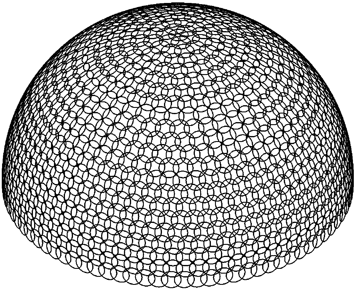
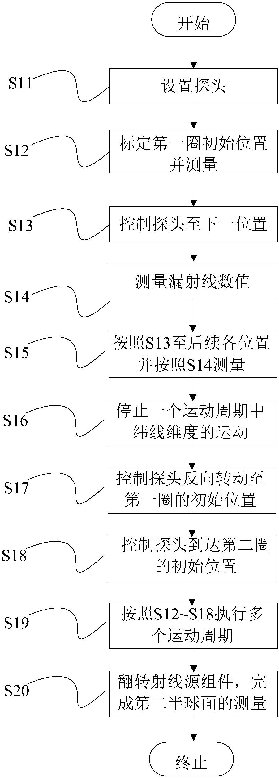
The invention provides a radiation leakage test method and equipment for a radiation source component, which can realize the radiation leakage test at the lowest possible cost. The method of the present invention includes: setting a probe at a position with a predetermined distance from the focal point; controlling the probe to execute a plurality of motion cycles with the focal point as the center of the sphere and moving in the dimensions of longitude and latitude, so as to seamlessly envelop the first hemispherical surface ; After the ray source component is turned over, the second hemisphere is seamlessly enveloped and merged to form the entire sphere. The device of the present invention comprises a first rotating arm, a second rotating arm, a probe, a mounting seat of a radiation source assembly, a first driving unit and a second driving unit, and the mounting seat, the first rotating arm and the second rotating arm are rotatable in turn connection, the probe is installed on the rotating end of the second rotating arm, and is used to measure the leakage ray value at each position where it has stayed; the rotating axes of the first rotating arm and the second rotating arm are perpendicular to each other, and intersect the axis of the main body of the probe at the ray The focal point of the source, and the probe is at a predetermined distance from the focal point.

Description

technical field [0001] The invention relates to the technical field of radiation leakage testing, in particular to a method and equipment for radiation leakage testing of radiation source components. Background technique [0002] The radiation source component is composed of a radiation source and a beam limiter, which is an important part of CT products, and the radiation leakage test of the radiation source component is a necessary test for CT products. [0003] According to the requirements of the relevant regulations on the radiation leakage test, the required measurement range is a spherical surface with a radius of 1 meter with the focal point of the radiation source in the measured radiation source assembly as the center of the sphere. [0004] One method of the prior art is to arrange 18 square probes that meet the requirements of the regulations to form a semicircular probe group in a staggered manner, so that the distance from all probes to the center of the semici...

Claims


Application Information

Patent Timeline
Patent Type & Authority Patents(China)
IPC IPC(8): G01T7/00
CPCG01T7/00G01N23/046G01T1/2985
Inventor 李双学祝一鸣于军
Owner NEUSOFT MEDICAL SYST CO LTD
Learn More