
Total station instrument and lofting and guiding method thereof

A total station and working method technology, applied in the direction of instruments, surveying instruments, surveying and navigation, etc., can solve the problems of large uncertain position range, short distance, laser safety power limited divergence angle, etc., and achieve high reliability and precision , the effect of convenient process

Pending Publication Date: 2017-05-17
CHANGZHOU XINRUIDE INSTR
View PDF6 Cites 7 Cited by
  • Summary
  • Abstract
  • Description
  • Claims
  • Application Information

AI Technical Summary

Problems solved by technology

[0002] The traditional stakeout guide uses two beams of different colors with a certain divergence angle to indicate. The characteristics of the two beams are distributed on the left and right sides of the collimation axis, and they do not interfere with each other. With different flicker frequencies, the target placement personnel observe the beam The target is placed at the junction position. This method solves the problem that when the target is far away from the measurement position, it can be quickly placed to a closer position to the approximate stakeout point. The disadvantage is that due to the large range of unsure positions of the beam observed by the human eye, the final placement is accurate. It needs to be realized by the observers on the instrument side directing the target placement personnel through the walkie-talkie, which is time-consuming and laborious
The speed of light is limited by the safe power and has a large divergence angle, so the distance that can be measured is mostly within 150 meters. In case of strong sunlight background outside, the distance that can be observed becomes shorter
[0003] The traditional excavation guiding device of the pipe jacking machine uses the laser beam of the laser beam to aim at the target position, and controls the direction of pipe jacking excavation by observing the relative changes between the target object and the position of the laser point. The disadvantage is that it is limited by the laser safety power and With a certain divergence angle, the general visible distance is within 300 meters, and the greater the distance, the larger the laser point, and the larger the indication error will be.

Method used


Image

  • Total station instrument and lofting and guiding method thereof

Examples


Embodiment 1

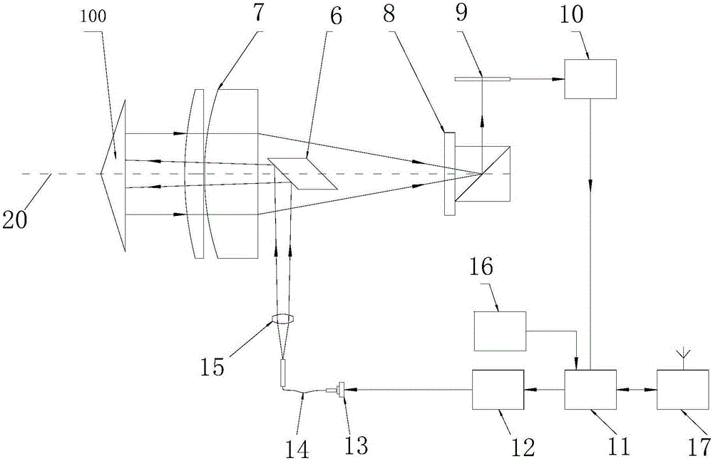
[0017] like figure 1 , the total station of the present embodiment includes: a driver 12 and a laser 13 connected to the processor unit 11 in turn, the output optical path of the laser 13 is successively provided with a launch optical fiber 14, a collimator for compressing the laser light into a bunch of collimated light Lens 15, reflective element 6 and objective lens 7; reflective element 6 and objective lens 7 have a common central axis, and this central axis is the collimation axis 20 of total station; the rear side of reflective element 6 is coaxially provided with dichroic prism 8, which One side of 8 is provided with image sensor 9, and image sensor 9 is connected with image processor 10, and image processor 10 is connected with processor unit 11; During work, processor unit 11 (preferably ARM processor or computer) is controlled by driver 12 Laser 13 produces laser light, and this laser light passes through emitting fiber 14, collimator lens 15 successively, then passe...

Embodiment 2

[0023] The method of using the total station of the above-mentioned embodiment 1 for lofting guidance includes: erecting the total station in the construction channel, aiming at the direction of the stakeout point or the direction of pipe jacking and then not moving. Fix the reflective prism 100 on the collimation axis, and detect the position of the reflected light spot in the image in real time when the shield machine head is moving, calculate the deviation data between the orientation of the reflective prism 100 and the orientation of the collimation axis 20, and make The deviation data and the image are displayed in real time on the staff's mobile communication device, and the staff adjusts the traveling direction of the shield machine head in real time according to the deviation data and the image, so that the reflective prism 100 returns to the collimation axis , and then make the shield head travel along the collimation axis.

Embodiment 3

[0025] The method for stakeout guidance using the total station of the above-mentioned embodiment 1 includes: during construction stakeout, according to the construction drawing, erecting the total station in the reference station, aiming the total station at the direction of the required stakeout point on the construction drawing and then not moving , the target placement staff moves the reflective target 100 to the collimation axis, the instrument detects the position of the reflected light spot in the image in real time, calculates the deviation data between the orientation of the reflective target 100 and the orientation of the collimation axis 20, and makes The deviation data and the image are displayed in real time on the staff's mobile communication device, and the staff moves the reflective target 100 to the collimation axis of the instrument according to the deviation data and image instructions, and the front and rear distance between the reflective target 100 and the ...


PUM


Abstract

The invention relates to a total station instrument and a lofting and guiding method thereof. The total station instrument comprises a driver and a laser device which are successively connected with a processor unit, wherein emission optical fiber, a collimating lens used for compressing laser into a beam of collimating laser, a reflecting component and an objective lens are successively arranged on an output laser path of the laser device; a beam splitter prism is coaxially arranged on the rear side of the reflecting component; an image sensor is arranged on one side of the beam splitter prism and is connected with an image processor; the image processor is connected with the processor unit; the processor unit is used for controlling the laser device to generate laser through the driver; the laser successively passes through the emission optical fiber and the collimating lens, then the laser successively passes through the reflecting component and the objective lens to form parallel laser, and the parallel laser is emitted out; the laser is reflected back after meeting a reflecting prism at a target end and is emitted to the image sensor through the objective lens and the beam splitter prism; then reflection laser spots are formed in the image sensor; and then the image processor can obtain an image with reflection laser spots and send the image to the processor unit.

Description

technical field [0001] The invention relates to a total station and a method for coordinating construction lofting and excavation guidance of a pipe jacking machine. Background technique [0002] The traditional stakeout guide uses two beams of different colors with a certain divergence angle to indicate. The characteristics of the two beams are distributed on the left and right sides of the collimation axis, and they do not interfere with each other. With different flicker frequencies, the target placement personnel observe the beam The target is placed at the junction position. This method solves the problem that when the target is far away from the measurement position, it can be quickly placed to a closer position to the approximate stakeout point. The disadvantage is that due to the large range of unsure positions of the beam observed by the human eye, the final placement is accurate. It needs to be realized by the observers on the instrument side directing the target p...

Claims


Application Information

Patent Timeline
Patent Type & Authority Applications(China)
IPC IPC(8): G01C15/00
CPCG01C15/00
Inventor 祁俊王峰
Owner CHANGZHOU XINRUIDE INSTR
Learn More