
High-pressure self-sealing valve

A self-closing, high-pressure technology, applied in valve device, valve details, valve shell structure, etc., can solve the problems of complex internal structure, poor reliability of self-closing function, large valve volume, etc., and achieve the effect of simple structure

Active Publication Date: 2017-05-17
XIAN ANCN INTELLIGENT INSTR +1
View PDF7 Cites 4 Cited by
  • Summary
  • Abstract
  • Description
  • Claims
  • Application Information

AI Technical Summary

Problems solved by technology

[0003] In order to overcome the above-mentioned shortcomings, the purpose of the present invention is to provide a high-pressure self-closing valve in the field, so as to solve the technical problems of existing valves with large volume, complex internal structure and poor reliability of self-closing function

Method used


Image

  • High-pressure self-sealing valve
  • High-pressure self-sealing valve

Examples


Embodiment Construction

[0014] Now in conjunction with accompanying drawing, the present invention will be further described.

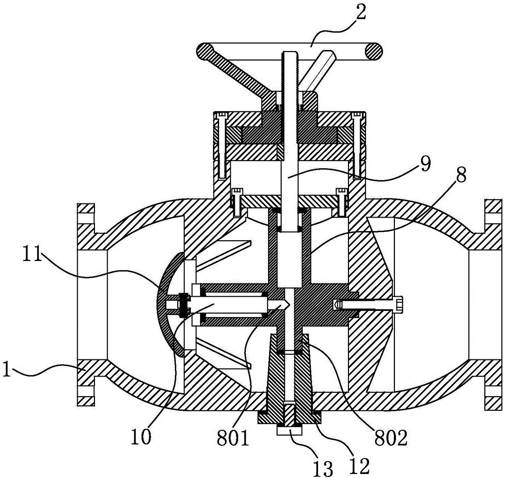
[0015] Such as figure 1 As shown, the high-pressure self-closing valve includes a valve body 1, a valve core assembly, a hand wheel 2, a hand wheel limiting plate 3, a hand wheel positioning plate 5, a guiding positioning plate 6, and a sealing plate 7. The valve body is provided with an inlet 101, an outlet 102, and an operating port 103, and the inlet and the outlet are straight-through, and the operating port is vertical relative to the straight-through direction. The valve body is provided with a connected front bracket 104 and a rear bracket 106. The internal wall is strengthened and fixed by triangular ribs, the front bracket is provided with a valve port 105 leading to the inlet and the outlet along the straight direction from the inlet to the outlet, and the rear bracket is provided with a port connecting the inlet and the outlet. A spool assembly is arranged betwee...


PUM


Abstract

The invention relates to a high-pressure self-sealing valve. The high-pressure self-sealing valve comprises a valve body, a hand wheel and a valve cover. The valve body is provided with an inlet, an outlet and an operation opening. A front bracket and a back bracket which are siamesed are arranged in the valve body. The front bracket is provided with a valve port. The back bracket is provided with a through opening. A cylinder body, a valve rod and a cylinder rod are arranged between the front bracket and the back bracket. The cylinder body is fixed to the back bracket and provided with two sections of communicating hydraulic cavities which are formed in an included angle mode. One section of hydraulic cavity is provided with the sliding telescopic cylinder rod which faces towards the operation opening, and the other section of hydraulic cavity is provided with the sliding telescopic valve rod which faces towards the valve port. The cylinder rod is directional sliding relative to the valve body. The hand wheel is positioned rotating relative to the valve body. The hand wheel is in thread fit with the cylinder rod. The end, stretching out of the cylinder body, of the valve rod is connected with the valve cover used for sealing the valve port of the front bracket. When rotated, the hand wheel pushes the cylinder rod to compress the hydraulic cavities in the cylinder body and then pushes the valve rod to drive the valve cover to open the valve port, so that valve breakover is achieved. Conversely, self sealing of the valve cover under the stress of the inlet of the valve body is achieved, and sealing is reliable.

Description

technical field [0001] The invention relates to a valve, which is a high-pressure self-closing valve. Background technique [0002] Valves are the control components in the fluid delivery system. They have the functions of cut-off, adjustment, flow diversion, reverse flow prevention, pressure stabilization, flow diversion or overflow pressure relief. Generally, it is necessary to select a suitable valve according to the requirements of the fluid system delivery. Existing valve control methods are usually divided into manual, hydraulic, electric or pneumatic, but in these existing control methods, the power part is usually directly linked with the valve head part of the valve, that is, the transmission method is relatively direct. For example, hydraulic control uses a hydraulic pump as a power component, and uses hydraulic pressure to push the valve stem connected to the valve head, directly driving the valve head to open and close the valve. For example, the authorized anno...

Claims


Application Information

Patent Timeline
Patent Type & Authority Applications(China)
IPC IPC(8): F16K21/04F16K31/14F16K31/12F16K27/02
CPCF16K21/04F16K27/02F16K31/12F16K31/14
Inventor 黄继亭王少彬叶笼汉
Owner XIAN ANCN INTELLIGENT INSTR
Learn More