Synchronization signal sending method, synchronization signal detection method, base station and terminals
A technology of synchronization signal and transmission method, applied in the fields of base station and terminal, synchronization, synchronization signal transmission and detection method, can solve the problems of increasing the power consumption and synchronization time of the receiving end, the limited energy of synchronization signal, and reducing the efficiency of narrowband system.
- Summary
- Abstract
- Description
- Claims
- Application Information
AI Technical Summary
Problems solved by technology
Method used
Image
Examples
Embodiment 1
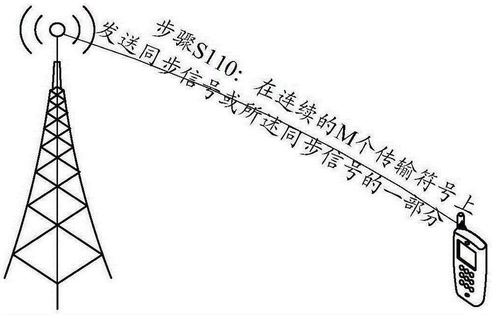
[0121] Such as figure 1 As shown, this embodiment provides a synchronization signal transmission method, the method comprising:
[0122] Step S110: sending a synchronization signal or a part of the synchronization signal on consecutive M transmission symbols;
[0123] Wherein, the M is an integer not less than 2;
[0124] The transmission symbol includes a cyclic prefix and a useful symbol part; the content carried in the cyclic prefix is the last part of content carried by the useful symbol.
[0125] The synchronization signal sending method described in this embodiment can be applied to a base station. The method described in this embodiment is especially applicable to narrowband transmission. In this embodiment, the synchronization signal or a part of the synchronization signal is sent in M transmission symbols. In this way, the receiving end can receive synchronization signals from at least M transmission symbols, which can improve the receiving gain, thereby impro...
Embodiment 2
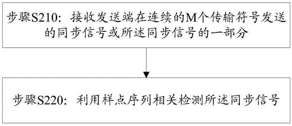
[0155] Such as figure 2 As shown, this embodiment provides a synchronization signal detection method, the method includes:
[0156] Step S210: Receive the synchronization signal or a part of the synchronization signal sent by the transmitting end in consecutive M transmission symbols; wherein, the M is an integer not less than 2; the transmission symbol includes a cyclic prefix and a useful symbol part; The content carried in the cyclic prefix is the last part of the content carried by the useful symbol;
[0157] Step S220: Detect the synchronization signal by using sample sequence correlation.
[0158] The method for detecting a synchronization signal described in this embodiment is applied to a receiving end, and is usually applied to a terminal such as a mobile phone. In this embodiment, the receiving end in step S210 will continuously receive M transmission symbols at one time. And from the received M transmission symbols, the synchronization signal is detected throu...
example 1
[0182] Figure 3A with Figure 3B A schematic diagram of sending a synchronization signal on consecutive M=3 transmission symbols is given in , and the contents of the three transmission symbols are the same; the content of the cyclic prefix and the useful symbol part of the three transmission symbols are respectively consistent. Figure 3A The cyclic prefix length of the transmitted symbols shown in Figure 3B The transmission symbols shown are prefixed differently. Assume that at a specific sampling frequency, the useful symbol part of all transmission symbols in transmission mode 1 includes N=7 samples (a, b, c, d, e, f, g), and the cyclic prefix part includes L=2 samples point, both are (f,g). In transmission mode 2, the useful symbol part of all transmission symbols includes N=7 samples (a, b, c, d, e, f, g), and the cyclic prefix part includes L=3 samples, both of which are (e , f, g).
[0183] For the above synchronization signal transmission, the synchronization s...
PUM
 Abstract
Description
Claims
Application Information
 - R&D Engineer
- R&D Manager
- IP Professional
- Industry Leading Data Capabilities
- Powerful AI technology
- Patent DNA Extraction
Browse by: Latest US Patents, China's latest patents, Technical Efficacy Thesaurus, Application Domain, Technology Topic, Popular Technical Reports.
© 2024 PatSnap. All rights reserved.Legal|Privacy policy|Modern Slavery Act Transparency Statement|Sitemap|About US| Contact US: help@patsnap.com


