
Auxiliary working platform of substation transformer

A technology for auxiliary work and transformers, applied in the direction of electrical components, switchgear, etc., can solve the problems of different dimensions, heat dissipation system structure, difficulty in main transformation, troubles, etc., to achieve flexible and changeable construction methods, convenient hanging parts, and easy lifting powerful effect

Active Publication Date: 2017-05-10
STATE GRID HENAN ELECTRIC ZHOUKOU POWER SUPPLY +1
View PDF4 Cites 2 Cited by
  • Summary
  • Abstract
  • Description
  • Claims
  • Application Information

AI Technical Summary

Problems solved by technology

At present, the transformers in UHV and EHV substations are huge, and some meters and valves are located on the top of the transformers, which is extremely inconvenient for maintenance and emergency repairs. The pebbles are smooth and uneven, and cannot be placed firmly, posing a safety hazard
In addition, pebbles are even more slippery in rainy days, which can easily cause people to fall
[0003] In order to facilitate the inspection and maintenance of the transformer, the staff wanted to set up a platform on site, but considering the complex surrounding conditions and the high risk of the transformer, it is difficult to reserve a permanent inspection platform on the main transformer, so scaffolding needs to be erected on site for each inspection.
However, due to the transformer structure and other reasons, there are the following problems in scaffolding construction: 1. Below the construction point of disconnection and re-leading are transformer radiators, pipelines, and control systems. It may be different from batch to batch, or due to transformation, there are different dimensions and heat dissipation system structures, and it is impossible to make a set of universal quick scaffolding. If it is made separately according to each transformer, the equipment procurement cost will be doubled; 3. Using Although steel pipe / bamboo springboard scaffolding is low in cost and flexible in structure, it has defects such as limited bearing capacity, long construction period, and easy damage to the transformer heat dissipation system or bushing.
However, this invention does not take into account the complex circuit at the top of the transformer, and the upper circuit needs to be removed during use, which is troublesome

Method used


Image

  • Auxiliary working platform of substation transformer
  • Auxiliary working platform of substation transformer
  • Auxiliary working platform of substation transformer

Examples


Embodiment 1

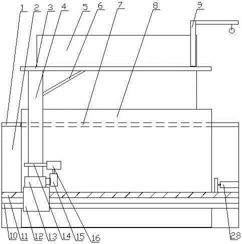
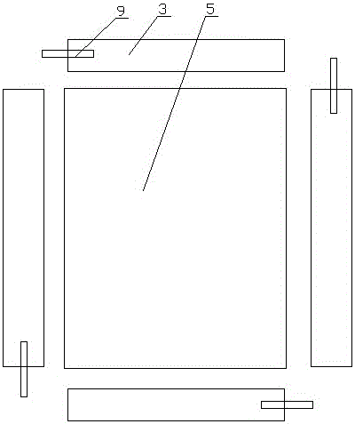
[0032] Such as Figure 1 to Figure 4 As shown: this embodiment provides a substation transformer auxiliary working platform, including a pit foundation 2, a transformer foundation 8 arranged in the center of the pit foundation 2, a transformer 5 arranged on the foundation 8, and the top of the pit foundation 2 A steel frame platform 1 is provided, a tank body 7 is arranged around the transformer 5, a cover plate mechanism 3 is arranged on the tank body 7, and a lifting mechanism for driving the cover plate mechanism 3 is set below one end of the tank body 7, so The lifting mechanism is arranged on the translation mechanism, and the front end of the cover mechanism 3 is provided with an L-shaped hanger 9 movably.

[0033]This embodiment is intended to solve the problems of inconvenient assembly of transformer body parts in the prior art, such as difficult maintenance. Firstly, a steel frame platform is set above the pit foundation. Flatness above pit foundation. The tank body...

Embodiment 2

[0037] Such as Figure 5 Shown: its difference with embodiment one is:

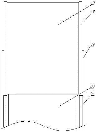
[0038] The L-shaped hanger 9 is movably arranged on the front end of the second bottom plate 17, and the front end of the second cross arm 18 is movably provided with a docking mechanism; Pipes 23, a third bottom plate 22 is arranged between the fixed pipes 23; a rotating base 26 is arranged at the front end of the second bottom plate 17, and a fixed socket 27 is arranged on the rotating base 26 corresponding to the L-shaped hanger 9 .

[0039] There are four tanks around the transformer, and the corresponding four cover mechanisms, the front end of the second cross arm is movable to set the docking mechanism, so that the height of the cover mechanism is higher than that of the transformer, and the two corresponding cover mechanisms are rotated Afterwards, their front ends can be butted together, so as to build a platform for hanging and maintenance above the transformer, so as to realize the maintenanc...

Embodiment 3

[0041] Such as figure 1 Shown: its difference with embodiment one is:

[0042] The lifting mechanism includes a hydraulic lifting column 4 and a supporting base 13 that is rotatably connected to the lower end of the hydraulic lifting column 4. A drive motor 15 is arranged on the supporting base 13, and an annular rack 14 is arranged at the bottom of the hydraulic lifting column 4. The driving motor 15 is connected to the ring rack 14 through a reduction box 16 in transmission.

[0043] The translation mechanism includes a lead screw 11, a translation motor 28 for driving the lead screw 11 and a fixed rod 10 matched with the lead screw 11, and a slider 12 is sleeved on the lead screw 11 and the fixed rod 10, so that The support base 13 is provided on the slider 12; the outer surface of the screw 11 and the fixed rod 10 is provided with a graphite lubricating layer.

[0044] The lifting mechanism adopts a hydraulic lifting column, which has stronger lifting strength and better...


PUM


Abstract

The invention discloses an auxiliary working platform of a substation transformer. The auxiliary working platform comprises a pit base, a transformer foundation arranged in the center of the pit base, a transformer arranged on the foundation, and a steel frame platform arranged above the pit base, wherein a groove body is arranged around the transformer; the groove body is provided with a cover plate mechanism; a lifting mechanism used for driving the cover plate mechanism is arranged below one end of the groove body; the lifting mechanism is arranged on a translation mechanism; and an L-shaped hoisting frame is movably arranged at the front end of the cover plate mechanism. When the transformer is overhauled, specific equipment or part can be hoisted and moved without other hoisting equipment to perform an auxiliary operation, so that potential safety hazard caused by movement of a large-scale hoisting apparatus in the transformer can be avoided; and therefore, the transformer can be overhauled and maintained by a staff more conveniently, and safety of the overhaul operation is also improved.

Description

technical field [0001] The invention relates to the technical field of transformer auxiliary equipment, in particular to a substation transformer auxiliary working platform. Background technique [0002] The substation is an important node of the power grid, which plays a role of linking the past and the future. The normal operation of the substation largely depends on the normal operation of the transformer. At present, the transformers in UHV and EHV substations are huge, and some meters and valves are located on the top of the transformers, which is extremely inconvenient for maintenance and emergency repairs. The pebbles are smooth and uneven, and cannot be placed firmly, posing safety hazards. In addition, pebbles are even more slippery in rainy days, which can easily cause people to fall. [0003] In order to facilitate the inspection and maintenance of the transformer, the staff wanted to set up a platform on site, but considering the complex surrounding conditions ...

Claims


Application Information

Patent Timeline
IPC IPC(8): H02B3/00
CPCH02B3/00
Inventor 刘阳马学民潘涛
Owner STATE GRID HENAN ELECTRIC ZHOUKOU POWER SUPPLY
Learn More