A 10kv switch cabinet
A switchgear and cabinet body technology, applied in the field of 10kV switchgear, can solve the problems of low safety and achieve the effects of improving safety, reducing data loss, and facilitating analysis
- Summary
- Abstract
- Description
- Claims
- Application Information
AI Technical Summary
Problems solved by technology
Method used
Image
Examples
Embodiment 1
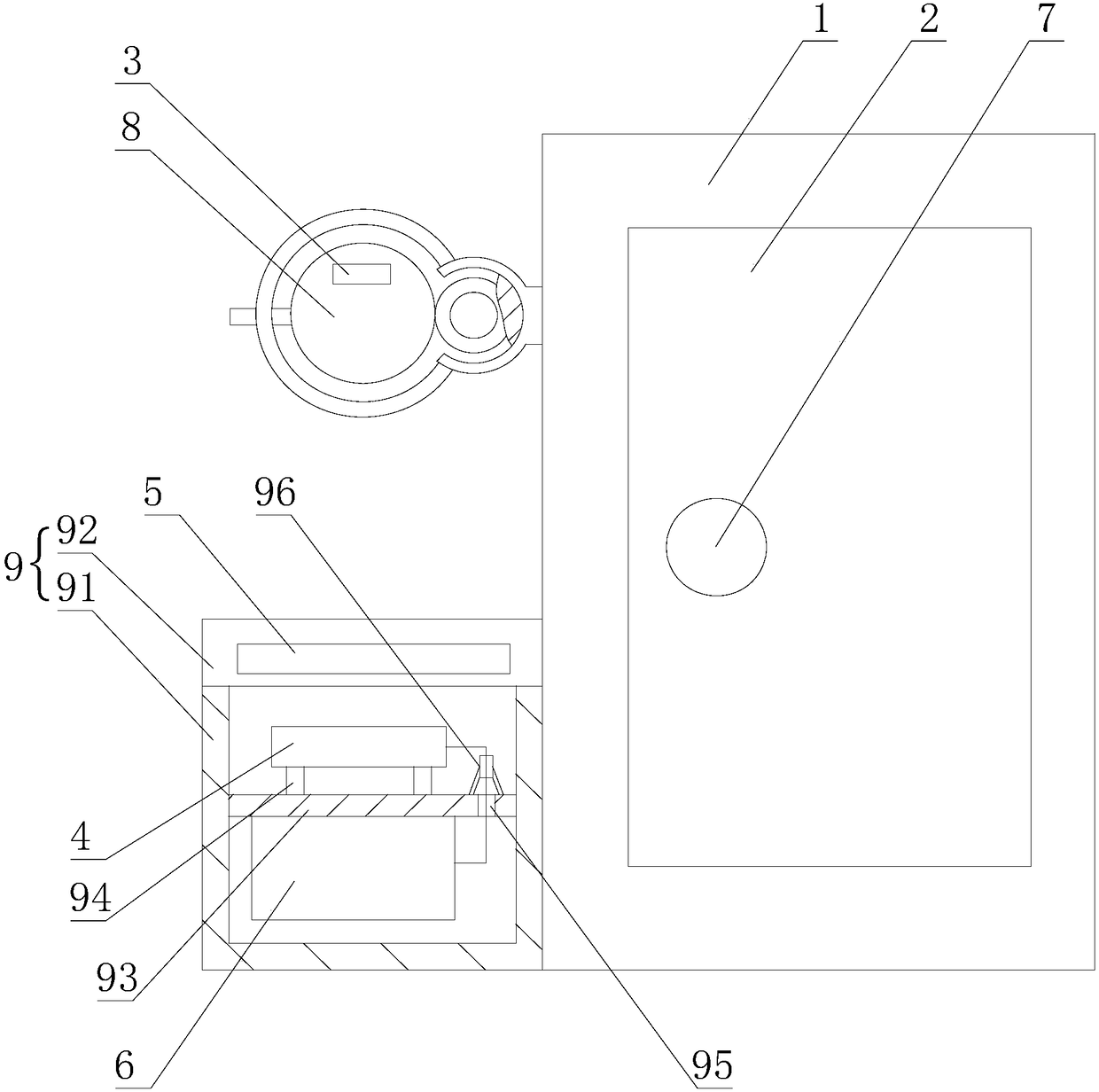
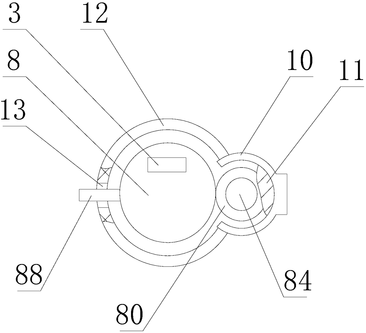
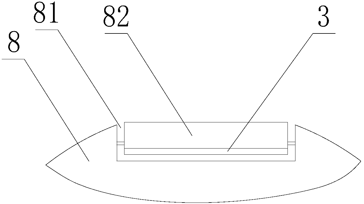
[0028] Such as figure 1 , figure 2 , image 3 As shown, a 10kV switch cabinet includes a cabinet body 1 and a cabinet door 2. The cabinet body 1 is provided with a live code sheet 3 whose content of the two-dimensional code can be modified, and the cabinet body 1 is provided with a scanner for scanning the live code sheet 3. 4. The scanner 4 is connected to a display 5, and the scanner 4 is connected to a power supply component 6. The scanner 4 scans the live code sheet 3 to obtain the text and picture prompts of the switch cabinet, and displays the danger source through the display 5. The cabinet door 2 is arranged on the cabinet body 1 through the electronic lock 7, and the power supply component 6 is electrically connected with the electronic lock 7.
[0029] The live code piece 3 is arranged on the cabinet body 1 through the connecting rod 8, which is convenient to install and disassemble, and has a simple structure. The fixing plate 82 at one end of the groove 81 can ...
Embodiment 2
[0033] A 10kV switch cabinet as described in Embodiment 1, this embodiment has the following differences: as Figure 4 As shown, the connecting rod 8 is provided with a connecting sleeve 83, and the connecting sleeve 83 is connected to the connecting rod 8 by thread rotation, and the live code chip 3 is arranged on the connecting rod 8 facing the connecting sleeve 83, which saves costs and is reliable in connection. Preventing the damage of the live code chip can ensure the clarity of the live code chip, and it is convenient for the scanner to obtain the relevant information of the switch cabinet.
[0034] When in use, the guide block 80 slides in the guide sleeve 10 to realize the guide sliding of the connecting rod 8 on the cabinet 1. When the power contact 84 contacts the limit plate 11, the power supply assembly 6 is turned on to realize the scanning of the scanner 4. and the power supply of the electronic lock 7, then open the cover 92, take the scanner 4 to scan the live...
Embodiment 3
[0036] As a kind of 10kV switchgear as described in the first and second embodiments, this embodiment has the following differences: as Figure 5 As shown, the connecting rod 8 is fixedly connected to the cabinet body 1, the connecting rod 8 is provided with a button switch 85, the button switch 85 is connected with the power supply assembly 6, the conduction and disconnection of the power supply assembly 6 are controlled by the button switch 85, and the button switch 85 is used to control the power supply assembly 6. The switch realizes the conduction and disconnection of the power supply components, which is convenient for maintenance personnel to operate.
[0037]When in use, press the button switch 85 to enable the power supply assembly 6 to supply power to the scanner 4 and the electronic lock 7, then open the cover 92, take the scanner 4 to scan the live code sheet 3, and the text obtained by the scanned piece 4 and picture prompts are displayed through the display 5, an...
PUM
 Abstract
Description
Claims
Application Information
 - R&D
- Intellectual Property
- Life Sciences
- Materials
- Tech Scout
- Unparalleled Data Quality
- Higher Quality Content
- 60% Fewer Hallucinations
Browse by: Latest US Patents, China's latest patents, Technical Efficacy Thesaurus, Application Domain, Technology Topic, Popular Technical Reports.
© 2025 PatSnap. All rights reserved.Legal|Privacy policy|Modern Slavery Act Transparency Statement|Sitemap|About US| Contact US: help@patsnap.com


