Self-locking device of rotary socket

A technology of self-locking device and socket, which is applied in the direction of preventing contact with live contacts, flexible/rotatable wire connectors, electrical components, etc., can solve the problems that the rotating core does not have the self-locking function and reduces the safety performance of rotation, etc. Achieve the effect of avoiding electric shock and improving safety performance

Active Publication Date: 2017-05-10
泉州市天文通网络科技有限公司
View PDF7 Cites 3 Cited by
  • Summary
  • Abstract
  • Description
  • Claims
  • Application Information

AI Technical Summary

Problems solved by technology

[0002] The rotary socket solution provided in the prior art mainly adopts the method of rotary locking or rotary unlocking to turn on the power supply, and uses the pressure generated by the rotation to lock and fix the plug. Please refer to CN103151665A, CN200983455 Y, the existing rotary core There is no self-locking function, which reduces the safety performance of rotation, and its safety factor still has room for improvement

Method used


Image

  • Self-locking device of rotary socket
  • Self-locking device of rotary socket
  • Self-locking device of rotary socket

Examples


Embodiment Construction

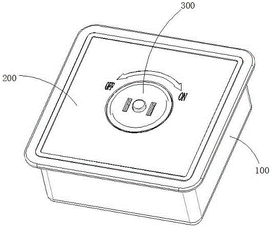
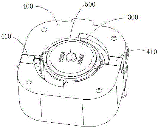
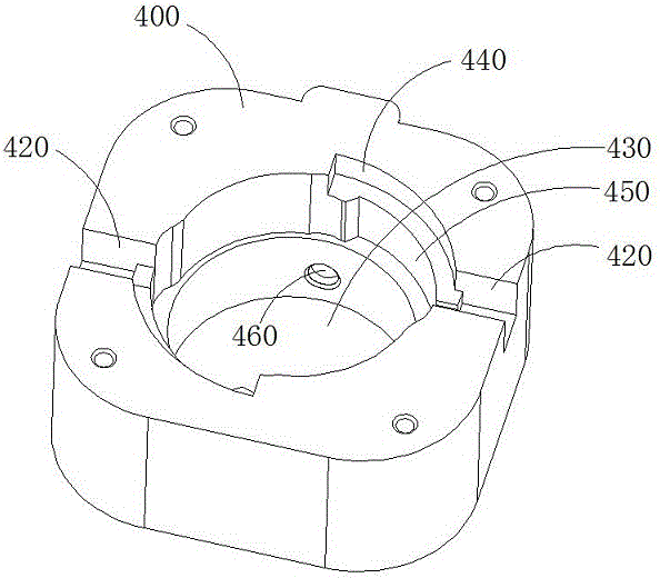
[0026] Such as Figure 1-12 As shown, the anti-electric shock intelligent self-locking socket includes a support body 400, a rotating core 300 that is sleeved in the support body 400 and can rotate around its own axis, a self-locking device 500 installed on the rotating core 300, and the center of the support body 400 There is a rotation hole 430 at the position, and the rotation hole 430 includes an upper rotation hole and a lower rotation hole. The rotation core 300 matches the lower rotation hole of the rotation hole 430 and can rotate around its own axis. Mounting grooves 420 arranged symmetrically at both ends of the hole, the central axes of the mounting grooves 420 at both ends are located on the same extension line and pass through the central axis of the rotating hole 430, and the lower rotating hole is provided with locks arranged symmetrically at both ends of the support body 400 Tight hole 460, the central axes of the locking holes 460 at both ends are located on t...


PUM


Abstract

The invention discloses a self-locking device of a rotary socket. The self-locking device comprises a center guide hole, a center guide post, a contact bump arranged at the top of the center guide post, and a pair of locking push blocks matched with the bottom of the center guide post, wherein the center guide post and the center guide hole are concentrically arranged; a spring sleeves the outside of the center guide post and is arranged between a limiting step and the contact bump; the bottom of the center guide post is connected with a trapezoid push bump; the trapezoid push bump is inverted; the locking push blocks are C-shaped; each locking push block comprises a first push block, a second push block and a third push block; one end of each second push block is vertical to one end surface of the corresponding first push block and the other end of each second push block is vertical to the corresponding third push block; each third push block is provided with a push inclined plane toward the corresponding first push block; each push inclined plane is matched with the inclined plane of the trapezoid push bump; the opening directions of the pair of locking push blocks are opposite and in crossed distribution; and the push inclined planes of the pair of locking push blocks are arranged oppositely.

Description

technical field [0001] The invention provides a self-locking structure of a socket, in particular a self-locking device suitable for electric shock-proof sockets in homes or factories. Background technique [0002] The rotary socket solution provided in the prior art mainly adopts the method of rotary locking or rotary unlocking to turn on the power supply, and uses the pressure generated by the rotation to lock and fix the plug. Please refer to CN103151665A, CN200983455 Y, the existing rotary core There is no self-locking function, which reduces the safety performance of rotation, and its safety factor still has room for improvement. Contents of the invention [0003] The purpose of the present invention is to improve the existing rotary socket by adding a self-locking function to the rotary core to further improve its safety level and significantly reduce the possibility of accidental electric shock. [0004] In order to realize the above-mentioned technical purpose, th...

Claims


Application Information

Patent Timeline
Patent Type & Authority Applications(China)
IPC IPC(8): H01R35/00H01R13/44
CPCH01R13/44H01R35/00
Inventor 朱文祥
Owner 泉州市天文通网络科技有限公司
Why Eureka
Try Eureka