Interconnected commutated board card integration and heat dissipation integrated control box

A technology of control boxes and boards, which is applied in connection, cooling/ventilation/heating transformation, coupling devices, etc., which can solve the problem of affecting the stability of signal external interconnection transfer performance, the liquid-cooled cold plate cannot dissipate heat from the back of the device, and the circuit board cannot be solved. Problems such as double-sided heat dissipation, to solve the problem of double-sided heat dissipation, simple structure, good air tightness

Inactive Publication Date: 2017-05-10
SHANGHAI AEROSPACE SCI & IND ELECTRIC APPLIANCE RES INST
View PDF6 Cites 4 Cited by
  • Summary
  • Abstract
  • Description
  • Claims
  • Application Information

AI Technical Summary

Problems solved by technology

However, the cold plate heat dissipation method currently used is mainly to arrange the heat-generating devices on the printed board in a centralized manner, and to arrange them on one side of the printed board as much as possible. When some of the heat-generating devices are on the back of the printed board, the liquid-cooled cold plate cannot pass through. The back area dissipates heat from the back device
[0003] The electronic circuit board control box in the prior art cannot solve the problem of heat dissipation on both sides of the circuit board, the modular integration degree is low, and the heat dissipation effect is poor, which greatly affects the performance stability of the signal external interconnection transfer

Method used


Image

  • Interconnected commutated board card integration and heat dissipation integrated control box
  • Interconnected commutated board card integration and heat dissipation integrated control box
  • Interconnected commutated board card integration and heat dissipation integrated control box

Examples


Embodiment Construction

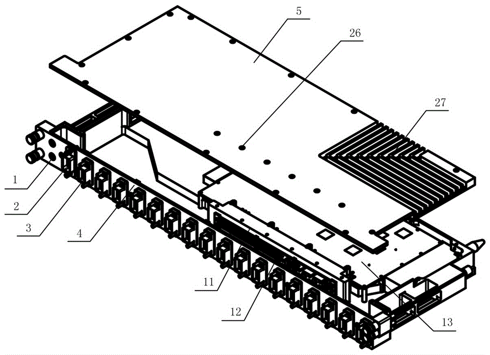
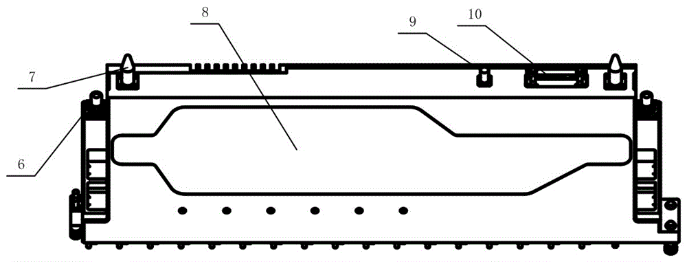
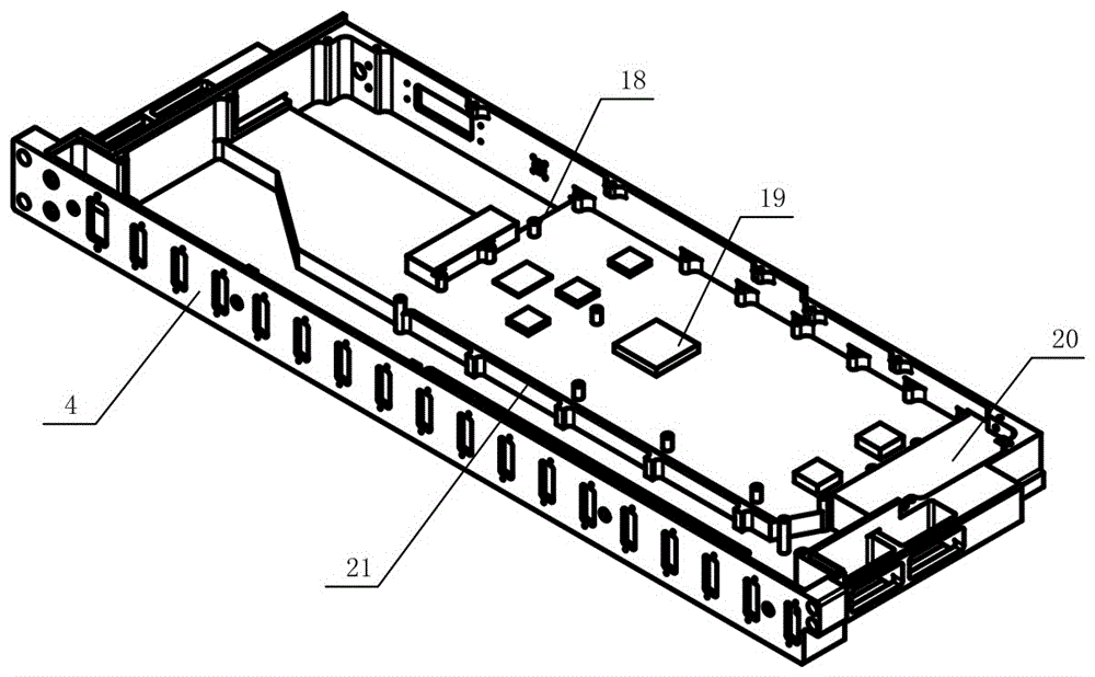
[0011] See attached figure 1 ~ attached figure 2 , the present invention is composed of a box body 4, a cooling cover plate 5, a liquid cooling cover plate 8 and a circuit board 13, and the circuit board 13 is arranged in the box body 4 provided with a liquid cooling flow channel 22 and a liquid cooling fin 23 and consists of The cooling cover plate 5 and the liquid cooling cover plate 8 are packaged into a heat dissipation integrated control box; the outer sides of the box body 4 are respectively provided with an indicator light 1, a power connector 2, a photoelectric hybrid connector 3, and a fluid connector 6 , guide post 7, radio frequency connector 9, comprehensive mixed connector 10, LRM connector mounting bracket 11 and LRM connector socket 12; the indicator light 1 is used for power supply indication and working status indication of the entire product; The power connector 2 is used to supply power to the circuit board 13; the photoelectric mixed connector 3, the rad...


PUM


Abstract

The invention discloses an interconnected commutated board card integration and heat dissipation integrated control box. The control box is characterized in that a circuit board is arranged in a box body which is provided with a liquid cooling flow channel and a liquid cooling fin, and is encapsulated by a cold guiding cover plate to form an integrated control box; the liquid cooling fin is arranged in the liquid cooling flow channel which is provided with a liquid inlet and a liquid outlet; and the liquid cooling flow channel is arranged on the outside bottom of the box body and is encapsulated by a liquid cooling cover plate. Compared with the prior art, the control box has the advantages of being simple in structure, small in volume, good in airtightness, high in insulation and voltage resistance value and wide in application range, can be directly butted with a flexible needle to satisfy the requirements for the quick release of the flexible needle and the weldability of a shell, is capable of skillfully solving the assembling problem of the circuit board and effectively solving the double-side heat dissipation problem of the circuit board, has a characteristic of blind plugging, and is an interconnected commutated board card which integrates the modularization, efficient integration and heat dissipation.

Description

technical field [0001] The invention relates to the technical field of electrical connector packaging shells, in particular to a control box integrated with board card integration and heat dissipation for interconnection and transfer. Background technique [0002] In the field of computer technology application, electronic circuit boards will generate a lot of heat when they are working. Using liquid-cooled cold plates to dissipate heat is currently a mainstream trend to solve the heat dissipation of electronic circuit board products. However, the cold plate heat dissipation method currently used is mainly to arrange the heat-generating devices on the printed board in a centralized manner, and to arrange them on one side of the printed board as much as possible. When some of the heat-generating devices are on the back of the printed board, the liquid-cooled cold plate cannot pass through. The backside area dissipates heat from the backside devices. [0003] The electronic c...

Claims


Application Information

Patent Timeline
Patent Type & Authority Applications(China)
IPC IPC(8): H01R12/72H01R13/46H05K7/20
CPCH01R12/722H01R13/46H05K7/20272H05K7/20409
Inventor 金旸霖谭伟
Owner SHANGHAI AEROSPACE SCI & IND ELECTRIC APPLIANCE RES INST
Why Eureka
Try Eureka