Intelligent wearable electronic equipment
An electronic device and smart wearable technology, applied in circuits, electrical components, antenna supports/installation devices, etc., can solve the problems of inability to meet antenna wiring requirements, antenna performance degradation, antenna wiring area reduction, etc., and achieve a compact structure. , The effect of ensuring the performance of the antenna and increasing the wiring area
- Summary
- Abstract
- Description
- Claims
- Application Information
AI Technical Summary
Problems solved by technology
Method used
Image
Examples
Embodiment 1
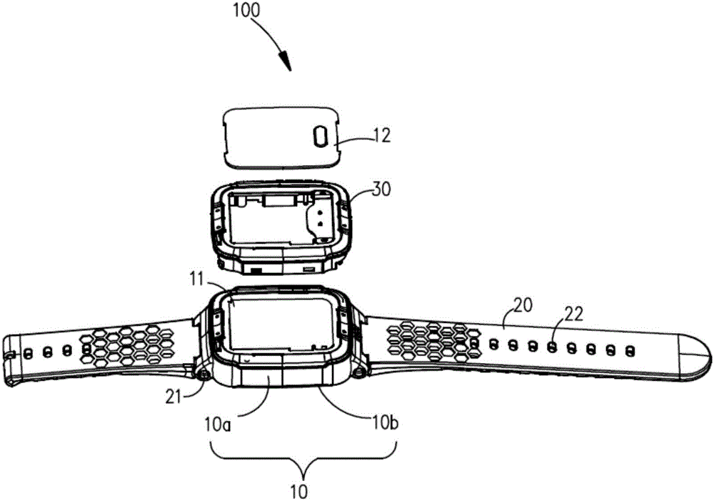
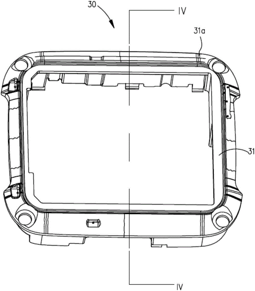
[0038] Please also refer to Figure 1 to Figure 4 , is a schematic structural diagram of a smart wearable electronic device 100 provided in Embodiment 1 of the present invention. The smart wearable electronic device 100 includes a dial part 10, a strap part 20 connected to the dial part 10, an antenna support 30 and an antenna (not shown) arranged on the dial part 10 or the strap part 20, and a circuit is arranged in the dial part 10 The main board 11 and a battery (not shown) electrically connected to the main board 11 . The antenna bracket 30 has an antenna arrangement surface 31 which is an uneven surface, the antenna is disposed on the antenna arrangement surface, and the antenna is electrically connected to the circuit board.
[0039] In this embodiment, the smart wearable electronic device 100 may be a smart watch or a smart bracelet.
[0040] In this embodiment, the dial part 10 can be made of metal material, such as aluminum alloy or stainless steel. Certainly, the ...
Embodiment 2
[0059] Please also refer to Image 6 and Figure 7 , is a schematic structural diagram of the smart wearable electronic device provided by Embodiment 2 of the present invention. The difference between the smart wearable electronic device provided in Embodiment 2 of the present invention and the smart wearable electronic device in Embodiment 1 of the present invention is that:
[0060] The strap part 20 is made of non-metallic material. The strap part 20 is provided with a cavity (not shown) extending along the length extension direction of the strap part 20. The antenna bracket 30 is arranged in the cavity and covers the cavity. The antenna arrangement surface 31 is the top surface of the antenna bracket 30 . In this embodiment, in order to prevent the antenna from being affected, the strap part 20 is made of non-metallic material, such as silicone, rubber or leather. In order to facilitate processing and reduce the processing technology, the antenna bracket 30 can be integ...
PUM
 Abstract
Description
Claims
Application Information
 - R&D
- Intellectual Property
- Life Sciences
- Materials
- Tech Scout
- Unparalleled Data Quality
- Higher Quality Content
- 60% Fewer Hallucinations
Browse by: Latest US Patents, China's latest patents, Technical Efficacy Thesaurus, Application Domain, Technology Topic, Popular Technical Reports.
© 2025 PatSnap. All rights reserved.Legal|Privacy policy|Modern Slavery Act Transparency Statement|Sitemap|About US| Contact US: help@patsnap.com


