
A directional LED light emitting element

A light-emitting device, directional technology, applied in electrical components, semiconductor devices, circuits, etc., can solve the problems of loss of light energy, low light efficiency, light reflection, etc., to reduce the loss of light energy, improve light efficiency, strengthen The effect of light energy

Active Publication Date: 2019-07-26
深圳市纽艾迪电子科技有限公司
View PDF1 Cites 0 Cited by
  • Summary
  • Abstract
  • Description
  • Claims
  • Application Information

AI Technical Summary

Problems solved by technology

[0004] Because the LED light source is a surface light source, unlike the traditional halogen light source, the LED light is not like a point light source with a light angle of 0°-360°. Generally, the LED light source can emit light in all directions close to 180 degrees. However, if the LED light source is close to When emitting light at 180 degrees, there must be some light emitted by the center of the LED light source that cannot be reflected through the inner surface of the reflective bowl, and part of the light will be reflected or refracted back to the LED light source itself, which consumes light energy and results in low light efficiency.

Method used


Image

  • A directional LED light emitting element
  • A directional LED light emitting element

Examples


Embodiment Construction

[0019] The following will clearly and completely describe the technical solutions in the embodiments of the present invention with reference to the accompanying drawings in the embodiments of the present invention. Obviously, the described embodiments are only some, not all, embodiments of the present invention. Based on the embodiments of the present invention, all other embodiments obtained by persons of ordinary skill in the art without creative efforts fall within the protection scope of the present invention.

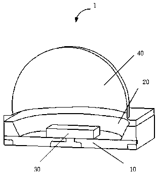
[0020] see figure 1 , a preferred embodiment of the present invention, a directional LED light-emitting element 1, including a substrate 10, a main reflector 20, an LED chip 30, and a sub-reflector 40, the main reflector 20 is a reflective bowl arranged on the substrate 10, The inner surface of the reflective bowl is a reflective surface, the LED chip 30 is arranged in the reflective bowl, and the secondary reflector 40 is arranged on the mouth of the reflective bo...


PUM


Abstract

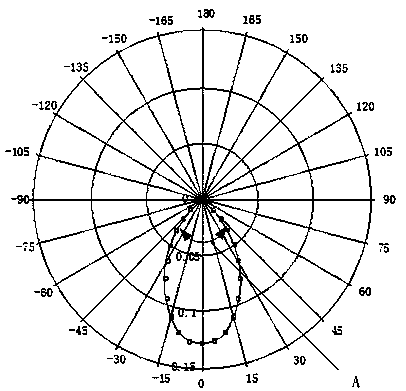
The present invention provides a directional LED light-emitting part. The directional LED light-emitting part comprises a substrate, a main reflector, an LED chip, a secondary reflector. The main reflector is a reflective bowl disposed on the substrate. The internal surface of the reflective bowl is a reflective surface. The LED chip is disposed in the reflective bowl. The secondary reflector is disposed on the bowl mouth of the reflective bowl. The secondary reflector is used for reflecting light emitted by the LED chip to the reflective surface of the reflective bowl. The light-emitting full-width of the light-emitting part is between 125 degree and 145 degree. Due to setting of the full-width of the LED light-emitting part, light energy loss is lowered to the greatest extent, light effect collimation is improved, and the directional LED light-emitting part furthest meets the application demands of terminal electronic products.

Description

technical field [0001] The invention relates to the field of light-emitting elements, in particular to a directional LED light-emitting element. Background technique [0002] With the development of LED technology, LED has been widely used in the field of lighting due to its high efficiency and energy saving characteristics. [0003] LED chips are light-emitting diodes (LEDs) as light sources. Light-emitting diodes are made of several layers of very thin doped semiconductor materials. One layer carries excess electrons, and the other layer forms positively charged "holes" due to lack of electrons. When a current passes through, the electrons and holes interact with each other. Combine and release energy, which radiates light. [0004] Since the LED light source is a surface light source, unlike the traditional halogen light source, the LED light is not like a point light source with a light angle of 0°-360°. Generally, the LED light source can emit light in all directions ...

Claims


Application Information

Patent Timeline
Patent Type & Authority Patents(China)
IPC IPC(8): H01L33/60
CPCH01L33/60
Inventor 何冠军
Owner 深圳市纽艾迪电子科技有限公司
Learn More