Sound intensity full-automatic measurement bracket and measurement method thereof

A measurement method and fully automatic technology, applied in measurement devices, measuring ultrasonic/sonic/infrasonic waves, instruments, etc., can solve problems such as high work intensity and inability to achieve fully automatic measurement, achieve convenient operation, reduce measurement costs, guarantee The effect of accuracy

Inactive Publication Date: 2017-05-10
ZHUZHOU TIMES NEW MATERIALS TECH
View PDF12 Cites 5 Cited by
  • Summary
  • Abstract
  • Description
  • Claims
  • Application Information

AI Technical Summary

Problems solved by technology

[0005] The sound intensity test bracket in the above-mentioned patent documents is a semi-automatic adjustment bracket, which cannot a...

Method used


Image

  • Sound intensity full-automatic measurement bracket and measurement method thereof
  • Sound intensity full-automatic measurement bracket and measurement method thereof
  • Sound intensity full-automatic measurement bracket and measurement method thereof

Examples


Embodiment 1

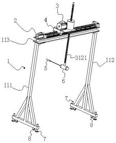
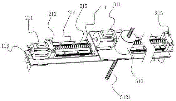
[0054] Embodiment 1: as figure 1 As shown, a sound intensity full-automatic measuring support includes a gantry support 1, a horizontal motor drive assembly 2, a lifting motor drive assembly 3, a horizontal slide table 4 and a probe holder 6 for fixing a sound intensity probe 5; The motor drive assembly 2 is arranged on the top of the gantry support 1, and the horizontal slide table 4 is slidably connected on the top of the gantry support 1. Driven by the horizontal motor drive assembly 2, the horizontal slide table 4 can move along the top of the gantry support 1. Sliding back and forth in the horizontal direction, the lifting motor driving assembly 2 is arranged on the horizontal slide table 4, the probe fixing clip 6 is connected to the lifting motor driving assembly 2, driven by the lifting motor driving assembly 2, the probe fixing clip 6 The sound intensity probe 5 can move up and down vertically. In this embodiment, the horizontal and vertical positions of the sound in...

Embodiment 2

[0076] Embodiment 2: as Figure 6 and Figure 7 As shown, compared with Embodiment 1, the difference is that in the measurement method of this embodiment, in order to further improve the accuracy of the measurement results, the vertical path and the horizontal path are improved, that is, the vertical path includes A plurality of vertical paths 9 parallel to each other and a semicircular path 11 between one end of the adjacent vertical path 9, the opening of the semicircular path 11 in the vertical path faces the vertical direction; the horizontal path includes a plurality of parallel paths. The horizontal path 10 and the semicircular path 11 between one end of the adjacent horizontal path 10, the opening of the semicircular path 11 in the horizontal path faces the horizontal direction. This embodiment only needs to be programmed according to the scanning path, and the above-mentioned measurement path containing a semicircular path can be completed by simultaneously opening an...


PUM


Abstract

The invention discloses a sound intensity full-automatic measurement bracket and measurement method thereof. The sound intensity full-automatic measurement bracket comprises a gantry bracket, a horizontal motor driving component, an elevating motor driving component, a horizontal slide table and a probe fixing clamp which is used for fixing a sound intensity probe. The horizontal motor driving component is arranged on the top part of the gantry bracket. The horizontal slide table is slidably connected on the top part of the gantry bracket. The horizontal slide table can slide back and forth on the horizontal direction along the top part of the gantry bracket under driving of the horizontal motor driving component. The elevating motor driving component is arranged on the horizontal slide table. The probe fixing clamp is connected on the elevating motor driving component. The probe fixing clamp and the sound intensity probe can move back and forth on the vertical direction under driving of the elevating motor driving component. The sound intensity full-automatic measurement bracket can perform full-automatic sound intensity measurement on the tested component according to the actual state of the tested component through cooperation with the sound intensity probe so that the working intensity of measurement personnel can be reduced and the accuracy of the measurement result can be enhanced.

Description

technical field [0001] The invention relates to an auxiliary tooling for measuring sound intensity and a method for measuring sound intensity using the auxiliary tooling, in particular to a fully automatic sound intensity measuring bracket and a measuring method thereof. Background technique [0002] With the continuous improvement of people's living standards and the continuous development of industrialization, people have higher and higher requirements for noise reduction, so more and more strict requirements are put forward for the sound insulation performance of automobiles, ships, aircrafts, buildings and other components. Component sound insulation performance The sound intensity method measurement standard ISO15186-1 stipulates that the sound intensity probe needs to scan continuously on the surface of the component. The traditional method is to scan the surface of the component with a hand-held probe. [0003] However, hand-held operation is time-consuming and labor-...

Claims


Application Information

Patent Timeline
IPC IPC(8): G01H17/00
CPCG01H17/00
Inventor 罗竹辉颜猛郭福林贺才春
Owner ZHUZHOU TIMES NEW MATERIALS TECH
Why Eureka
Try Eureka