
Optical-fiber low-coherence interference displacement demodulation device and method based on photoelectric oscillator

A photoelectric oscillator, low-coherence interference technology, applied in the direction of instruments, optical devices, measuring devices, etc., can solve the problems of small measurement range, poor long-term reliability and stability, and measurement accuracy only in the order of microns, and achieve system Effects of improved stability and simplified displacement demodulation method

Inactive Publication Date: 2017-05-10
SOUTHWEST JIAOTONG UNIV
View PDF8 Cites 43 Cited by
  • Summary
  • Abstract
  • Description
  • Claims
  • Application Information

AI Technical Summary

Problems solved by technology

The time scanning method can measure a large range, but due to the need to mechanically scan one of the mirrors, its long-term reliability and stability are poor, and the measurement accuracy is only on the order of microns
Space scanning uses linear array CCD devices for electrical scanning, which has high long-term reliability, but the pixels of linear array CCD are limited, and its measurement range is usually small, only tens of microns

Method used


Image

  • Optical-fiber low-coherence interference displacement demodulation device and method based on photoelectric oscillator
  • Optical-fiber low-coherence interference displacement demodulation device and method based on photoelectric oscillator
  • Optical-fiber low-coherence interference displacement demodulation device and method based on photoelectric oscillator

Examples


Embodiment Construction

[0028] The following will clearly and completely describe the technical solutions in the embodiments of the present invention with reference to the accompanying drawings in the embodiments of the present invention. Obviously, the described embodiments are only some, not all, embodiments of the present invention. Based on the embodiments of the present invention, all other embodiments obtained by persons of ordinary skill in the art without making creative efforts belong to the protection scope of the present invention.

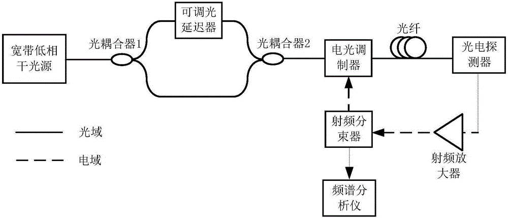
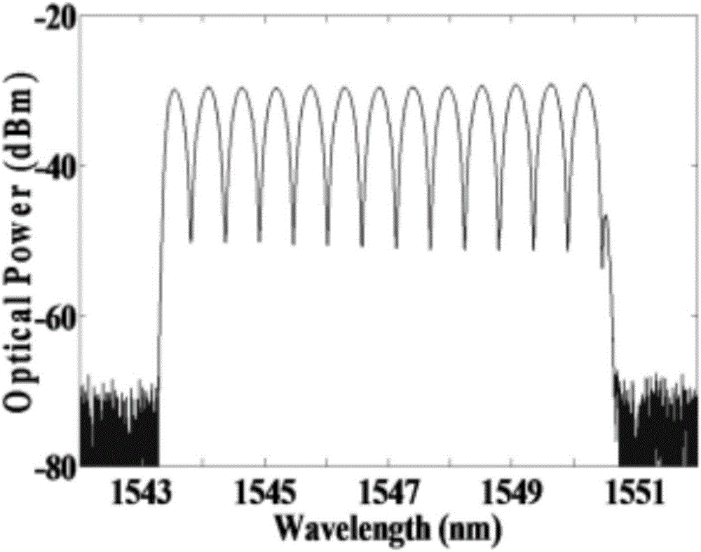
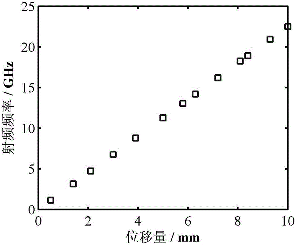
[0029] see figure 1 , is a schematic diagram of an optical fiber low-coherence interference displacement demodulation technology based on an optoelectronic oscillator according to an embodiment of the present invention. The system structure of this embodiment includes a broadband low-coherence light source, a first fiber coupler, an adjustable optical retarder, a second fiber coupler, an electro-optic modulator, and a photodetector sequentially connected throu...


PUM


Abstract

The invention provides an optical-fiber low-coherence interference displacement demodulation device and method based on a photoelectric oscillator. A first optical fiber coupler, an adjustable light delayer and a second optical fiber coupler form a Mach-Zehnder interferometer structure, and broadband low-coherence light generates an interference light field for output through the Mach-Zehnder interferometer structure. An electrooptical modulator, an optical fiber, a photoelectric detector, a radio-frequency amplifier and a radio frequency beam splitter form the photoelectric oscillator, and the photoelectric oscillator enables the inputted interference light field to be converted into a radio signal with high spectrum purity for output. The displacement change of a position device is obtained through the measurement of the frequency value of the radio frequency signal, thereby achieving the demodulation of the low-coherence interference displacement. The method provided by the invention can be used for the high-precision detection of displacement, or for other sensors to carry out the demodulation of stress, temperature, thickness, group index of refraction and pressure into displacement.

Description

technical field [0001] The invention relates to the field of displacement information demodulation, in particular to an optical fiber low-coherence interference displacement demodulation device based on a photoelectric oscillator and a demodulation method thereof. Background technique [0002] As an important non-contact measurement method, fiber optic low-coherence interferometry technology has broad application prospects in frontier fields such as non-contact measurement of optical systems and biomedical imaging due to its advantages of simple structure, fast measurement speed and high resolution. . [0003] Fiber-optic low-coherence interferometry usually consists of a Michelson interferometer illuminated by a broadband low-coherence light source. The optical path part is connected by single-mode optical fiber, and the laser light emitted by the low-coherence light source passes through the 2x2 optical fiber coupler, and then enters the reference arm with the mirror and ...

Claims


Application Information

Patent Timeline
IPC IPC(8): G01B11/02
CPCG01B11/02
Inventor 郑狄潘炜闫连山邹喜华
Owner SOUTHWEST JIAOTONG UNIV
Learn More