
Combined type HUD (Head Up Display) back light device

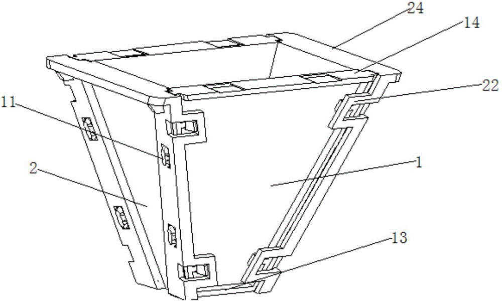
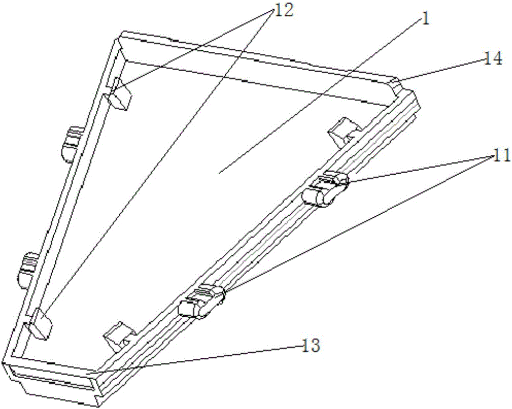
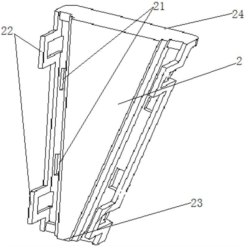
A backlight device and combined technology, which is applied to lighting devices, fixed lighting devices, and components of lighting devices, etc., can solve the complex optical coating process of HUD backlight devices, poor optical coating effect of HUD backlight devices, and low product quality rate. The problem is to overcome the complex optical coating process, improve the quality rate, and achieve the effect of simple structure.

Inactive Publication Date: 2017-05-10
FORYOU MULTIMEDIA ELECTRONICS
View PDF5 Cites 0 Cited by
  • Summary
  • Abstract
  • Description
  • Claims
  • Application Information

AI Technical Summary

Problems solved by technology

The existing HUD backlight device is an integrated or L-shaped interfitting device. Since the adjacent backlight panels of the HUD backlight device need excessive sharp corners to ensure the optical performance requirements of the HUD backlight device, the corners cannot be excessively rounded, resulting in an integrated The HUD backlight device of L-shaped or L-shaped mutual matching has sharp corners after molding. However, the sharp corners formed between adjacent backlight panels have very high requirements for molds and optical coatings, which makes the optical coating process of HUD backlight devices complicated. It is prone to problems such as poor optical coating effect of HUD backlight device, low product quality rate and high production cost

Method used


Image

  • Combined type HUD (Head Up Display) back light device
  • Combined type HUD (Head Up Display) back light device
  • Combined type HUD (Head Up Display) back light device

Examples


Embodiment Construction

[0011] The implementation of the present invention will be described in detail below in conjunction with the accompanying drawings. The accompanying drawings are only for reference and description, and do not constitute a limitation to the protection scope of the present invention.

[0012] An embodiment of the present invention provides a combined HUD backlight device, comprising at least two first trapezoidal backlight panels and at least two second trapezoidal backlight panels, at least two first trapezoidal The sides of the second trapezoidal backlight panel are adjacent to form a pyramid structure, and the two sides of the first trapezoidal backlight panel or the second trapezoidal backlight panel are provided with at least four pins and four buckles symmetrically distributed; the second trapezoidal backlight panel Both sides of the second trapezoidal backlight panel or the first trapezoidal backlight panel are provided with pin holes that cooperate with the pins of the fi...


PUM


Abstract

The invention provides a combined type HUD (Head Up Display) back light device, which comprises at least two first trapezoid back light plates and at least two second trapezoid back light plates. Sides of the at least two oppositely arranged first trapezoid back light plates and the at least two oppositely arranged second trapezoid back light plates are adjoined to form a pyramid-shaped structure; at least four bolts and four fasteners distributed symmetrically are arranged on two sides of each first trapezoid back light plate or each second trapezoid back light plate; and bolt holes matched with the bolts of each first trapezoid back light plate or each second trapezoid back light plate and fastening positions matched with the fasteners of each first trapezoid back light plate or each second trapezoid back light plate are arranged on two sides of each second trapezoid back light plate or each first trapezoid back light plate. According to the combined type HUD back light device provided by the invention, an optical surface of the HUD back light device is divided into pieces of single planes, so that an optical filming process flow of the back light plates is simplified, the optical filming efficiency of the back light plates is improved, the satisfactory rate of optical filming of the back light plates is further improved, and the production cost of the HUD back light device is reduced.

Description

technical field [0001] The invention relates to the technical field of automobile head-up displays, in particular to a combined HUD backlight device. Background technique [0002] HUD (Head Up Display) is a head-up display, which is more and more widely used in automobiles. It avoids the need for the driver to look down to see the instrument information, making driving safer. The existing HUD backlight device is an integrated or L-shaped interfitting device. Since the adjacent backlight panels of the HUD backlight device need excessive sharp corners to ensure the optical performance requirements of the HUD backlight device, the corners cannot be excessively rounded, resulting in an integrated The HUD backlight device of L-shaped or L-shaped mutual matching has sharp corners after molding. However, the sharp corners formed between adjacent backlight panels have very high requirements for molds and optical coatings, which makes the optical coating process of HUD backlight devi...

Claims


Application Information

Patent Timeline
Patent Type & Authority Applications(China)
IPC IPC(8): F21S8/00F21V17/10G02B27/01
CPCF21S8/00F21V17/10G02B27/0101
Inventor 李应久
Owner FORYOU MULTIMEDIA ELECTRONICS
Learn More