
Method for selecting axis of large cavern under high ground stress condition

A technology of high in-situ stress and in-situ stress, applied in the directions of hydroelectric power generation, hydroelectric power station, geophysical measurement, etc., can solve the problems of large dip angle of the maximum principal stress, reduced influence of the maximum principal stress, and no good solution, etc. The effect of support measures and design risk reduction

Active Publication Date: 2017-05-10
POWERCHINA CHENGDU ENG
View PDF4 Cites 5 Cited by
  • Summary
  • Abstract
  • Description
  • Claims
  • Application Information

AI Technical Summary

Problems solved by technology

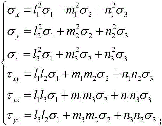
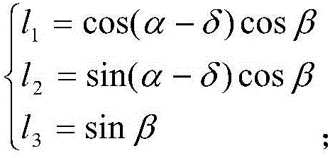
[0003] The in-situ stress state at any point in the project area can be represented by six independent in-situ stress components, namely three normal stress components and three shear stress components. When the three normal stress components are the main stresses, the three shear stress components are 0. The in-situ stress in the engineering area is actually a spatial in-situ stress field. How to choose the axis of the cavern to minimize the impact of the in-situ stress on the surrounding rock of the cavern has not been well resolved.
However, with the development of hydropower in the alpine and canyon areas of western my country, more and more underground caverns have been built under high ground stress conditions in recent years. Due to the influence of geological structure and terrain, there are situations where the maximum principal stress inclination angle is relatively large, such as Monkey Rock The measured maximum principal stress in the underground powerhouse area of ​​the hydropower station is 36.43MPa, and the inclination angle is 44.5°. In this case, the influence of the maximum principal stress on the horizontal direction is reduced. It is unreasonable to determine the axis of the cavern in the stress horizontal projection direction

Method used


Image

  • Method for selecting axis of large cavern under high ground stress condition
  • Method for selecting axis of large cavern under high ground stress condition
  • Method for selecting axis of large cavern under high ground stress condition

Examples


Embodiment

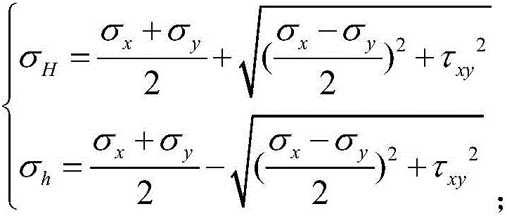
[0046] In order to verify that under the condition of high ground stress, the self-stabilization ability of the surrounding rock mass obtained by using the maximum horizontal stress direction as the reference standard of the cavern axis is stronger than that obtained by using the maximum principal stress horizontal projection direction as the reference standard, two test schemes are specially designed. Compared.

[0047] The two schemes use the same in-situ stress field (see Table 1), the same geological conditions, both use the Mohr-Coulomb constitutive model with tensile stress truncation, the same physical and mechanical parameters of the rock mass (see Table 2), the same cavern size, and the boundary Same conditions. Scheme 1 uses the maximum principal stress σ 1 The horizontal projection direction is the direction of the cavern axis (NW40.7°), and the maximum horizontal stress σ H The direction is the direction of the cavern axis (NW24.1°). The calculation process uses...


PUM


Abstract

The invention discloses a method for selecting the axis of a large cavern under a high ground stress condition, and belongs to the field of water conservancy and hydropower engineering. The method for selecting the axis of the large cavern under the high ground stress condition comprises the following steps that firstly, engineering geological investigation is conducted according to the scale of the underground cavern needing to be excavated, and thus actually-measured ground stress data and main structural surface characteristics of rock mass of the area where the cavern is located are obtained; secondly, different cavern axis determining methods are selected according to different ground stress levels; and finally, the axis of the cavern is determined with the direction of the maximum horizontal stress as the reference standard, and a small angle is formed between the axis of the cavern and the direction of the maximum horizontal stress. According to the method for selecting the axis of the large cavern under the high ground stress condition, the axis of the cavern is determined with the direction of the maximum horizontal stress as the reference standard through theoretical calculation, comprehensive analysis and experimental verification under the high ground stress condition and particularly under the condition that the maximum main stress angle is large, so that the self-stabilizing capacity of the rock mass around is made higher, the design risk can be greatly lowered accordingly, the number of support measures is reduced, and the purposes of economy and safety are achieved.

Description

technical field [0001] The invention relates to the field of water conservancy and hydropower engineering, in particular to a method for selecting the axis of a large cavern under high ground stress conditions. Background technique [0002] Underground cavern design includes cavern function design, layout design and excavation support design. Under the premise of meeting the functional requirements, the primary goal of cavern layout design and excavation support design is to ensure the stability of the surrounding rock of the cavern. The stability of the surrounding rock is maintained by two methods: one is the self-stabilization ability of the rock mass, and the other is the support measures. Therefore, the core idea of ​​the design of the cavern layout and the design of the excavation support is to give full play to the self-stabilization ability of the rock mass to reduce the support measures. The use of protective measures, so as to achieve the purpose of economy and saf...

Claims


Application Information

Patent Timeline
Patent Type & Authority Applications(China)
IPC IPC(8): E02B9/00G01V9/00
CPCE02B9/00G01V9/00Y02E10/20
Inventor 程丽娟廖成刚肖平西
Owner POWERCHINA CHENGDU ENG
Learn More