Optical fiber rub twist device

A technology of optical fiber and torsion wheel, applied in the field of auxiliary facilities, can solve problems such as large fluctuations in PMD value, fiber breakage, difficulties, etc., and achieve the effects of ensuring concentricity, good twisting effect, and reducing PMD

Active Publication Date: 2017-05-10
QINGHAI ZHONGLI OPTICAL FIBER TECH CO LTD
View PDF13 Cites 2 Cited by
  • Summary
  • Abstract
  • Description
  • Claims
  • Application Information

AI Technical Summary

Problems solved by technology

However, since the anti-frustration twisting device twists the optical fiber at a certain angle and speed by two twisting guide wheels, one in front and one behind, the flexibility of the rotation of the twisting guide wheels, surface quality and dynamic balance state etc. are extremely strict, and in actual use, it is often difficult to adjust the two twisting guide wheels to be in a good rubbing state for the optical fiber. More precisely, the user is required to have enough Professional level
In addition, under high-speed wire drawing conditions, it is easy to cause fiber breakage or large fluctuations in PMD value, and when the fiber breaks, the fiber will hit the twisting wheel, causing scratches on the twisting wheel, and once the twisting wheel is scratched, Then the scratch will scratch the fiber coating, and also cause the fiber to break during the drawing process

Method used


Image

  • Optical fiber rub twist device
  • Optical fiber rub twist device

Examples


Embodiment Construction

[0018] In order to understand the technical essence and beneficial effects of the present invention more clearly, the applicant will describe in detail the following examples, but the descriptions of the examples are not intended to limit the solutions of the present invention. Equivalent transformations that are only formal but not substantive should be regarded as the scope of the technical solution of the present invention.

[0019] In the following descriptions, all concepts involving directionality or orientation of up, down, left, right, front and rear are aimed at figure 1 As far as the position and state of the present invention are concerned, it cannot be understood as a special limitation on the technical solution provided by the present invention.

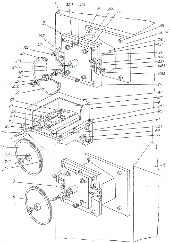
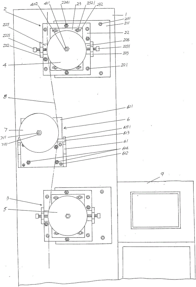
[0020] See figure 1 , showing a frame 1 that is generally in the shape of a cabinet; an upper positioning wheel support mechanism 2 and a lower positioning wheel support mechanism 3, the upper positioning wheel support ...


PUM


Abstract

The invention discloses an optical fiber rub twist device, and belongs to the technical field of auxiliary facilities in optical fiber production. The optical fiber rub twist device comprises a machine frame, a rub twist wheel reciprocate driving mechanism, and a rub twist wheel; an upper orientation wheel supporting mechanism and a lower orientation wheel supporting mechanism are arranged on the machine frame in an upper-lower opposite manner; an upper orientation wheel is arranged on the upper orientation wheel supporting mechanism, a lower orientation wheel is arranged on the lower orientation wheel supporting mechanism; the upper orientation wheel and the lower orientation wheel are arranged in an opposite manner; the rub twist wheel reciprocate driving mechanism is arranged on the machine frame between the upper orientation wheel supporting mechanism and the lower orientation wheel supporting mechanism; the rub twist wheel is connected with the rub twist wheel reciprocate driving mechanism; the distance from the upper orientation wheel to the rub twist wheel is equal to that from the lower orientation wheel to the rub twist wheel; optical fiber is introduced into the rub twist wheel via the upper orientation wheel, and is delivered out from the lower orientation wheel under rub twisting conditions by the rub twist wheel; the moving path of the optical fiber shapes like S. Damage of optical fiber is avoided, optical fiber coating layer concentricity is ensured, and optical fiber PMD is reduced effectively.

Description

technical field [0001] The invention belongs to the technical field of auxiliary facilities in optical fiber production, and in particular relates to an optical fiber twisting device. Background technique [0002] The purpose of twisting the optical fiber is to make the optical fiber rotate clockwise or counterclockwise at a certain frequency, number of turns and speed during the drawing process, thereby reducing the polarization mode dispersion of the optical fiber. The English abbreviation of polarization mode dispersion is PMD (English full name: Polarization Mode Dispersion). [0003] It is a common practice to set a pair of twisting devices at the end of the wire drawing equipment to twist the optical fiber to reduce the PMD value of the optical fiber, and experiments have proved that this measure has a good effect on reducing PMD. However, since the anti-frustration twisting device twists the optical fiber at a certain angle and speed by two twisting guide wheels, one...

Claims


Application Information

Patent Timeline
Patent Type & Authority Applications(China)
IPC IPC(8): C03B37/03
CPCC03B37/03Y02P40/57
Inventor 张国梁赵海林宋建鹏袁积鸿郑永宽盛小萍施蒙华
Owner QINGHAI ZHONGLI OPTICAL FIBER TECH CO LTD
Why Eureka
Try Eureka