


Quick Research
Generate reliable direction feasibility study reports for your R&D in just a few steps.

Technical Q&A
Discover and master advanced knowledge NOW. Basics, ideas, possibilities, all at once.

Find Solutions
As an expert in R&D theories, this can generate solutions to your technical problems instantly.

Evaluate Feasibility
Analyze your overall solution with one click, know your potential R&D risks in advance.

Monitor Landscape
Get weekly tech updates, stay abreast of the latest tech innovations and key insights.
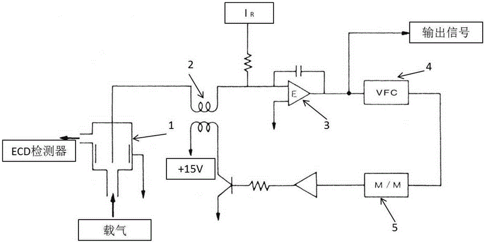
Sensitivity automatic detection method and device of electron capture detector
An electronic capture and detector technology, applied in the detection field, can solve the problems of reducing test efficiency and cumbersome adjustment process
- Summary
- Abstract
- Description
- Claims
- Application Information
AI Technical Summary
Problems solved by technology
Method used
Image

Examples
Embodiment Construction
[0045] In the following description, many technical details are proposed for readers to better understand the present invention. However, those skilled in the art can understand that even without these technical details and various changes and modifications based on the following embodiments, the technical solution required by each claim of the present invention can also be realized.
[0046]In order to make the purpose, technical solution and advantages of the present invention clearer, the following will further describe the implementation of the present invention in detail in conjunction with the accompanying drawings. In the following description of the drawings, the same or similar reference numerals designate the same or similar parts and components, and explanations may be omitted.
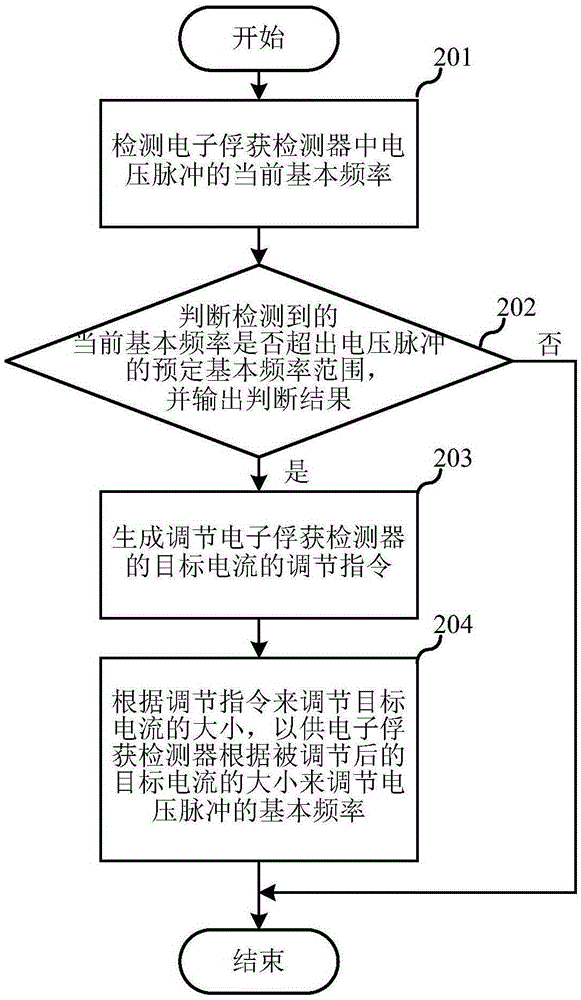
[0047] The first embodiment of the present invention relates to a method for automatically adjusting the sensitivity of an electron capture detector. figure 2 It is a schematic flow chart...
PUM
 Abstract
Description
Claims
Application Information
 - R&D Engineer
- R&D Manager
- IP Professional
- Industry Leading Data Capabilities
- Powerful AI technology
- Patent DNA Extraction
Browse by: Latest US Patents, China's latest patents, Technical Efficacy Thesaurus, Application Domain, Technology Topic, Popular Technical Reports.
© 2024 PatSnap. All rights reserved.Legal|Privacy policy|Modern Slavery Act Transparency Statement|Sitemap|About US| Contact US: help@patsnap.com