
Oil return preventing valve device for mechanical pump

A technology of mechanical pumps and oil valves, applied to mechanical equipment, parts of pumping devices for elastic fluids, pump components, etc., can solve problems such as glass stripping and waste products, and achieve the effect of improving product yield

Inactive Publication Date: 2017-05-03
陆雪峰
View PDF0 Cites 0 Cited by
  • Summary
  • Abstract
  • Description
  • Claims
  • Application Information

AI Technical Summary

Problems solved by technology

Oil stains must be absolutely avoided. The oil stains on the substrate will be clearly reflected on the coated glass after coating, resulting in glass stripping and waste products.

Method used


Image

  • Oil return preventing valve device for mechanical pump
  • Oil return preventing valve device for mechanical pump

Examples


Embodiment Construction

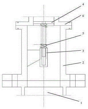
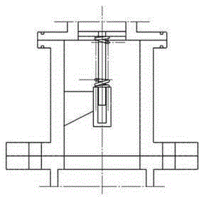
[0012] As shown in Figure 1, a mechanical pump anti-slip valve device according to the present invention includes a mechanical pump 1, an inlet cavity 2, a support mechanism 3, an anti-slip valve 4, a spring 5 and an inlet pipe 6.

[0013] The mechanical pump 1 and the inlet pipe 6 are connected through the inlet chamber 2, which is the function connection port of the mechanical pump anti-oil return valve device, and the inlet pipe 6 is arranged above the inlet chamber 2. The supporting mechanism 3 is fixed in the inlet cavity 2 and is a device supporting the reciprocating movement of the piston. The anti-slip valve 4 is connected with the support mechanism 3 through the spring 5, which is the core part of the whole device. The anti-slip valve 4 reciprocates on the support mechanism 3 under the action of the spring 5 through the pressure difference in the inlet cavity to realize The function of automatically isolating the pump chamber and the inlet pipe 6.

[0014] Working pr...


PUM


Abstract

The invention discloses an oil return preventing valve device for a mechanical pump. The oil return preventing valve device comprises the mechanical pump, an inlet cavity, a supporting mechanism, an oil return preventing valve, a spring and an inlet pipeline. The mechanical pump and the inlet pipeline are connected through the inlet cavity. The inlet pipeline is arranged above the inlet cavity. The supporting mechanism is fixed in the inlet cavity. The oil return preventing valve is connected with the supporting mechanism through the spring and does reciprocating motion on the supporting mechanism under the action of the spring through the pressure difference in the inlet cavity, so that a pump cavity and the inlet pipeline are automatically isolated. The oil return preventing valve device for the mechanical pump has the positive effects that communication and isolation of the mechanical pump cavity and the inlet pipeline are achieved under the action of the oil return preventing valve similar to a piston; the phenomenon that reverse pumping and oil return of the mechanical pump are prone to occurring due to the fact that the inlet pressure is smaller than the pump cavity pressure when the mechanical pump is applied to a high vacuum pump set is avoided; and when the mechanical pump is applied in the vacuum coating field, the problem that a demolding waste product is produced due to the fact that a substrate is polluted by oil stains can be solved, and the product yield is increased.

Description

technical field [0001] The invention relates to the technical field of vacuum equipment, in particular to a mechanical pump anti-oil valve device which can be applied to mechanical pumps such as rotary vane pumps and screw pumps, and relates to a large-area flat glass coating vacuum pump group. Background technique [0002] It is known that a combination of various vacuum pumps is required to obtain a high vacuum. A single pump cannot obtain a vacuum of l×l0-7mbar or higher. In the application of large-area flat glass coating, the glow discharge of the target needs to reach 3×l0-3mbar in the environment of Ar gas, and the vacuum of the coating chamber needs to reach 5× in the absence of any gas. l0-6mbar or lower, in this case, it is necessary to introduce a multi-stage vacuum pump group to obtain high vacuum. [0003] It is known that the pressure difference between the high vacuum pump and the low vacuum pump will inevitably be generated during the operation of the high ...

Claims


Application Information

Patent Timeline
Patent Type & Authority Applications(China)
IPC IPC(8): F04C29/00
Inventor 陆雪峰
Owner 陆雪峰
Learn More