
Robot remote tool coordinate attitude automatic positioning device and its positioning method

A technology of automatic positioning and tool coordinates, applied in the field of robotics, to achieve the effect of complicated operation steps, saving manpower and time, and improving productivity

Active Publication Date: 2020-07-28
COMAU KUNSHAN AUTOMATION
View PDF1 Cites 0 Cited by
  • Summary
  • Abstract
  • Description
  • Claims
  • Application Information

AI Technical Summary

Problems solved by technology

[0003] In order to overcome the above-mentioned defects, the present invention provides a robot remote tool coordinate attitude automatic positioning device and its positioning method that solve the problem of positioning the robot remote tool coordinate system posture, making the whole process simple and easy to operate

Method used


Image

  • Robot remote tool coordinate attitude automatic positioning device and its positioning method
  • Robot remote tool coordinate attitude automatic positioning device and its positioning method

Examples


Embodiment approach

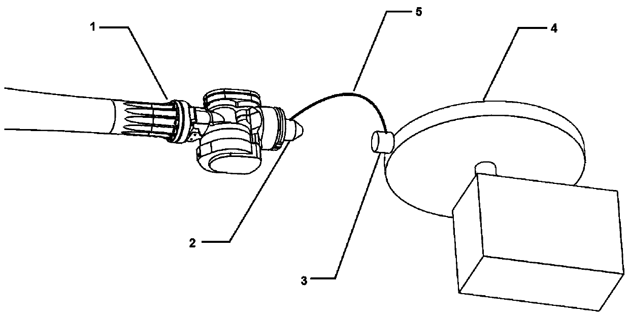
[0016] figure 2 Shows an embodiment of the robot remote tool coordinate posture automatic positioning device of the present invention, which includes a first test end 2 installed on the robot flange 1 and a second test installed on the center point of the remote tool 4 Terminal 3. The first test terminal 2 and the second test terminal 3 are connected by a data line 5. The first test terminal 2 is composed of a gyroscope sensor and a laser sensor, and the second test terminal 3 is a gyroscope. The first test terminal 2 and the second test terminal 3 are finally connected to the robot terminal through a data line.

[0017] Its robot remote tool coordinate posture automatic positioning method includes the following steps:

[0018] The first step is to obtain the posture of the center point of the remote tool: first, fix the first test end 2 on the flange of the robot, and fix the second test end 3 on the center point of the remote tool 4 for a while. Then, the robot The posture of ...


PUM


Abstract

The invention discloses a robot remote tool coordinate and posture automatic positioning device and a positioning method thereof. The robot remote tool coordinate and posture automatic positioning device comprises a first test terminal installed on a robot flange and a second test terminal installed on a remote tool center point. The first test terminal and the second test terminal are connected through a data line. The first test terminal is composed of a gyro sensor and a laser sensor. The second test terminal is a gyro sensor. The first test terminal and the second test terminal are finally connected with a robot terminal through a data line. By means of the non-contact type remote tool center point posture and coordinate automatic positioning device and the positioning method thereof, manpower and time are greatly saved, full-automatic positioning of coordinates and postures of a remote tool center point is achieved, labor force is liberated, and productivity is improved.

Description

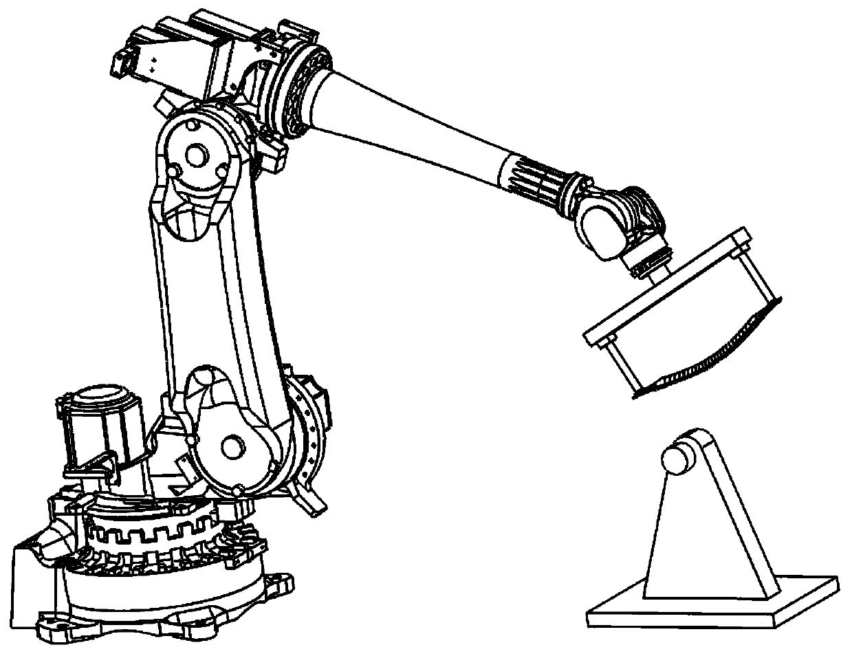
Technical field [0001] The invention relates to the technical field of robots, in particular to a robot remote tool coordinate posture automatic positioning device and a positioning method thereof. Background technique [0002] At present, in some robot applications, remote tools are used, such as grinding, polishing and deburring. Such as figure 1 As shown, the so-called remote tool means that the tool is fixedly installed on the ground and not on the execution end of the robot. However, how to locate the posture of the remote tool is more troublesome. Generally, 4 points are used at the tool center point. Method to measure its position and then determine its posture, this process is time-consuming, and the positioning posture of the tool is not accurate. Therefore, if a simple and accurate method is found to locate the posture of the tool coordinate system, it will shorten the debugging time of the robot and improve the production efficiency. Summary of the invention [0003] ...

Claims


Application Information

Patent Timeline
Patent Type & Authority Patents(China)
IPC IPC(8): B25J13/00B25J13/08
Inventor 陶宗杰
Owner COMAU KUNSHAN AUTOMATION
Learn More