
Rotary positioning device and positioning method for differential machine right shell

A technology of positioning device and positioning method, which is applied in the direction of positioning device, thread cutting device, thread cutting machine, etc., can solve the problems of inaccurate positioning and low efficiency, and achieve the effect of efficient and accurate positioning and accurate tapping.

Pending Publication Date: 2021-10-22
ZHEJIANG INFROTRONIC PRECISION MACHINE TOOL TECH CO LTD
View PDF0 Cites 0 Cited by
  • Summary
  • Abstract
  • Description
  • Claims
  • Application Information

AI Technical Summary

Problems solved by technology

[0004] At present, when tapping the screw hole of the right casing of the differential machine in the industry, it is usually done by manual positioning and tapping, which is inefficient and inaccurate in positioning. Therefore, a new solution needs to be proposed to solve the problem. This problem; at the same time, in order to better locate, it is necessary to improve the original right case of the differential machine. A scanning hole is set on the top outer wall between the two mounting bumps, and the scanning hole surrounds the top outer wall of the right case of the differential machine. At the same time, the width between the two mounting bumps where the scanning hole is located is greater than the width between the mounting bumps without the scanning hole

Method used


Image

  • Rotary positioning device and positioning method for differential machine right shell
  • Rotary positioning device and positioning method for differential machine right shell
  • Rotary positioning device and positioning method for differential machine right shell

Examples


Embodiment Construction

[0033] The present invention will be described in further detail below in conjunction with the accompanying drawings.

[0034] Wherein the same components are denoted by the same reference numerals. It should be noted that the words "front", "rear", "left", "right", "upper" and "lower" used in the following description refer to the directions in the drawings, and the words "bottom" and "top "Face", "inner" and "outer" refer to directions toward or away from, respectively, the geometric center of a particular component.

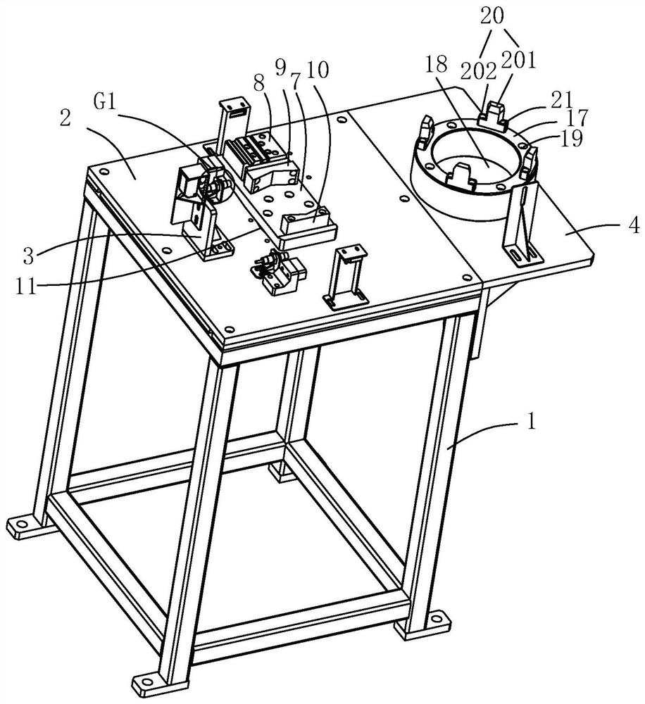
[0035] Such as Figure 1 to Figure 6 As shown, a rotary positioning device for the right shell of a differential machine includes a mounting frame 1, on which a mounting platform 2 is fixed, and a locator 3 is arranged on the mounting platform 2, and the locating instrument 3 is used for positioning the right side of the differential machine. Shell 26; one side of the locator 3 is provided with an angle adjustment device adapted to it; the side wall of the i...


PUM


Abstract

The invention discloses a rotary positioning device and a positioning method for a differential machine right shell, relates to the technical field of differential machines, and aims to solve the technical problems of low efficiency and inaccurate positioning during manual tapping of screw holes of the differential machine right shell. According to the technical scheme, the rotary positioning device for the differential machine right shell is characterized by comprising a mounting frame; a mounting table is fixed to the mounting frame, a positioning instrument is arranged on the mounting table, and the positioning instrument is used for positioning the differential machine right shell; an angle adjusting device matched with the positioning instrument is arranged on one side of the positioning instrument; and a side plate is arranged on the side wall of the mounting table, and a machining device is fixed to the side plate. Providing the rotary positioning device and the positioning method which are efficient and accurate in positioning is the purpose.

Description

technical field [0001] The technical field of the differential gear of the present invention, more specifically, it relates to a rotary positioning device and a positioning method for the right housing of the differential gear. Background technique [0002] The automobile differential can make the left and right driving wheels rotate at different speeds. It is mainly composed of the left and right side shaft gears, two planetary gears and the left and right housings. Make the left and right wheels roll at different speeds, that is, ensure the pure rolling motion of the driving wheels on both sides. [0003] The right housing of the differential machine usually includes a top and a bottom that are connected to each other. The top of the top is connected to a top plate, and the outer wall of the top is provided with several mounting bumps. [0004] At present, when tapping the screw hole of the right casing of the differential machine in the industry, it is usually done by ma...

Claims


Application Information

Patent Timeline
IPC IPC(8): B23G1/44B23Q3/00
CPCB23G1/44B23Q3/00
Inventor 潘春燕
Owner ZHEJIANG INFROTRONIC PRECISION MACHINE TOOL TECH CO LTD
Learn More