
Laundry-treatment appliance having a feeding device

A technology for clothing processing and supplying devices, applied in washing devices, household appliances, other washing machines, etc., can solve problems such as water and energy consumption, and achieve the effects of reducing water and energy consumption, reducing residual moisture, and reducing residual moisture.

Active Publication Date: 2017-04-26
BSH BOSCH & SIEMENS HAUSGERAETE GMBH
View PDF13 Cites 3 Cited by
  • Summary
  • Abstract
  • Description
  • Claims
  • Application Information

AI Technical Summary

Problems solved by technology

Traditional dehydration methods also consume relatively large amounts of water and energy

Method used


Image

  • Laundry-treatment appliance having a feeding device
  • Laundry-treatment appliance having a feeding device

Examples


Embodiment Construction

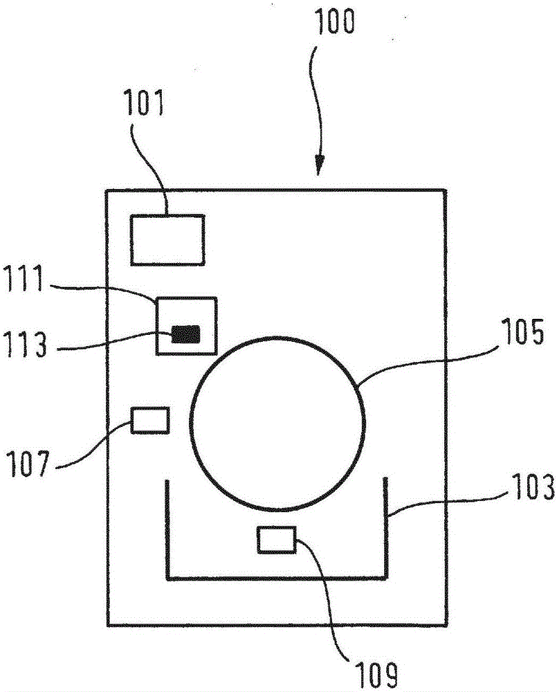
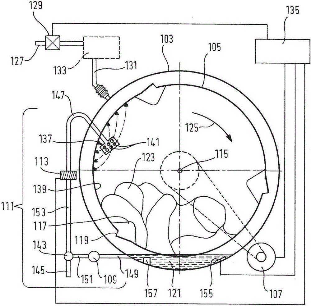
[0050] figure 1 A schematic diagram of a general laundry treating appliance 100, such as a washing machine, is shown. The laundry treating appliance 100 includes a storage container 101 into which detergent and other liquid substances can be introduced. When water is supplied into the storage container 101 and mixed there with detergent or other liquid substances, washing liquid required for the laundry treatment process is generated. The laundry treating appliance 100 part includes a tub 103 in which generated washing liquid is accommodated. A quantity of laundry can be introduced into the rotatably mounted washing drum 105 , at least a part of the washing liquid being guided into the tub 103 . The laundry treating appliance 100 comprises a drive 107 which drives the washing drum 105 and thereby enables the washing drum 105 to rotate.

[0051] The discharge pump 109 is configured to pump the washing liquid from the tub 103 and supply the washing liquid to the laundry in th...


PUM


Abstract

The present invention relates to a laundry-treatment appliance (100) for treating laundry (123), wherein the laundry-treatment appliance (100) comprises a tub (103) for accommodating washing detergent (121), a rotatably mounted washing drum (105) for accommodating laundry (123), a drive (107) for driving the washing drum (105), a detergent-solution pump (109) for pumping washing detergent (121) out of the tub (103), a feeding device (111) for feeding washing detergent (121) from the tub (103) into the washing drum (105), and a heat-generating device (113) for heating washing detergent (121) channelled through the feeding device (111). The detergent-solution pump (109) is designed so that, during a first period of time, a first quantity of washing detergent (121) can be pumped out of the tub (103). The drive (107) is designed so that, during a second period of time, which follows the first period of time, the washing drum (105) can be driven at a spinning frequency in order for a second quantity of washing detergent (121) to be spun off from the laundry (123) in the washing drum (105) and fed to the tub (103). The feeding device (111) is designed so that, during a third period of time, which follows the second period of time, the second quantity of washing detergent (121) can be fed from the tub (103) to the interior of the washing drum (105) in order to wet the laundry (123) in washing drum (105). The heat-generating device (113) is designed so that, during the third period of time, the second quantity of washing detergent (121) channelled through the feeding device (111) can be heated to a predetermined temperature, wherein the heat-generating device (113) is integrated in the feeding device (111). The drive (107) is designed so that, during the third period of time, the washing drum (105) can be driven at a rotational frequency in order for the second quantity of washing detergent (121) to be distributed in the laundry (123) located in the washing drum (105).

Description

technical field [0001] The invention relates to a laundry treating appliance having a supply device for supplying washing liquid from a tub to a washing drum. Background technique [0002] A laundry treatment process in a laundry treatment appliance, such as a washing machine, generally includes a washing phase followed by a centrifugal spinning phase with a plurality of centrifugal spinning cycles. During the washing phase, washing liquid is added to the dirty laundry in the rotatably mounted washing drum to clean the laundry. During the centrifugal spin cycle of the centrifugal spin phase, the washing drum rotates at a high centrifugal spin frequency. During this cycle, centrifugal force forces the washing liquid out of the laundry in the washing drum through the discharge holes in the washing drum into the intermediate space between the washing drum and the tub. The washing liquid thus separated may be accommodated in a tub of the washing machine. [0003] The centrifu...

Claims


Application Information

Patent Timeline
Patent Type & Authority Applications(China)
IPC IPC(8): D06F39/04D06F39/08
CPCD06F39/04D06F39/083D06F39/085
Inventor J·斯格里派克R·尤尔曼D·米施克T·伯特格R·勒默尔
Owner BSH BOSCH & SIEMENS HAUSGERAETE GMBH
Learn More