
A fully automatic lamination device for a Japanese-shaped or e1-shaped iron core of a transformer

A lamination device and transformer technology, applied in the manufacture of inductors/transformers/magnets, electrical components, manipulators, etc., can solve the problems of frequent boring repetitive actions, unstable product quality, low production efficiency, etc., and achieve compact structure and easy maintenance. Low cost and high versatility

Active Publication Date: 2018-09-04
CECEP ENVIRONMENTAL PROTECTION EQUIP CO LTD
View PDF5 Cites 2 Cited by
  • Summary
  • Abstract
  • Description
  • Claims
  • Application Information

AI Technical Summary

Problems solved by technology

[0003] The existing stacking process, whether it is a "day"-shaped iron core or an "E1"-shaped iron core, is manually stacked. The pure manual method not only has a high work intensity, but also has frequent boring and repetitive actions, low production efficiency and unstable product quality. , coupled with the current sharp increase in labor costs, transformer companies urgently need a fully automatic equipment that can replace manual lamination

Method used


Image

  • A fully automatic lamination device for a Japanese-shaped or e1-shaped iron core of a transformer
  • A fully automatic lamination device for a Japanese-shaped or e1-shaped iron core of a transformer
  • A fully automatic lamination device for a Japanese-shaped or e1-shaped iron core of a transformer

Examples


Embodiment 1

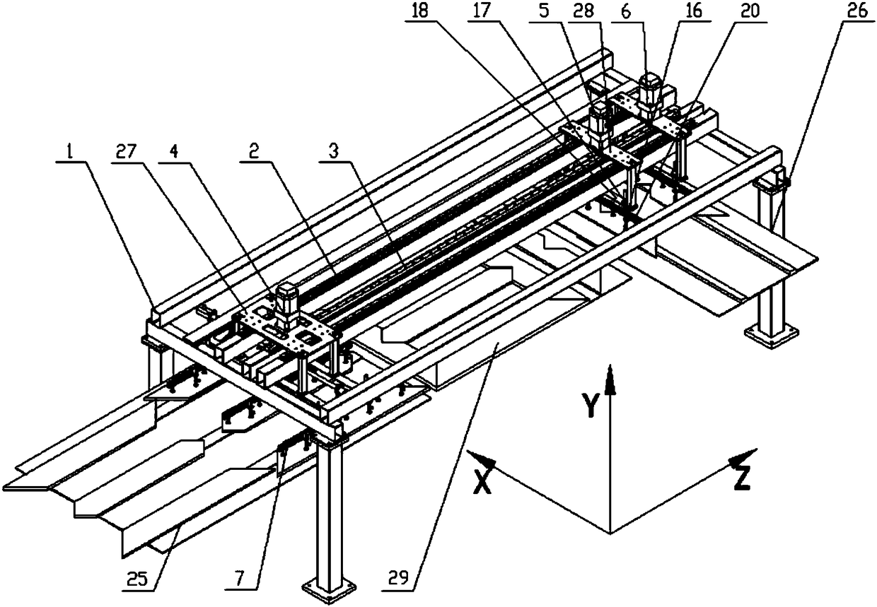
[0025] Such as figure 1 As shown, a fully automatic lamination device for a Japanese-shaped or E1 iron core of a transformer includes at least a lamination frame 1, a guide rail device 2 and a helical rack 3 that are fixed above the lamination frame 1 and arranged parallel to each other, and are installed along the guide rail. 2 and the three-column stack 4, the yoke column stack 5 and the upper yoke column stack 6 that move with the helical rack 3, the three-column stack 4, the yoke column stack 5 and the upper yoke column stack 6 are on the same straight line and They are respectively connected to the guide rail device 2, and the three-post stack 4, the yoke post stack 5 and the upper yoke post stack 6 are respectively driven by a set of servo system and helical gear 28, and the servo system includes a servo motor and a The reducer connected to the servo motor, the reducer is fixed on the servo connecting plate 27 and connected with the helical gear 28 through a tensioner sl...

Embodiment 2

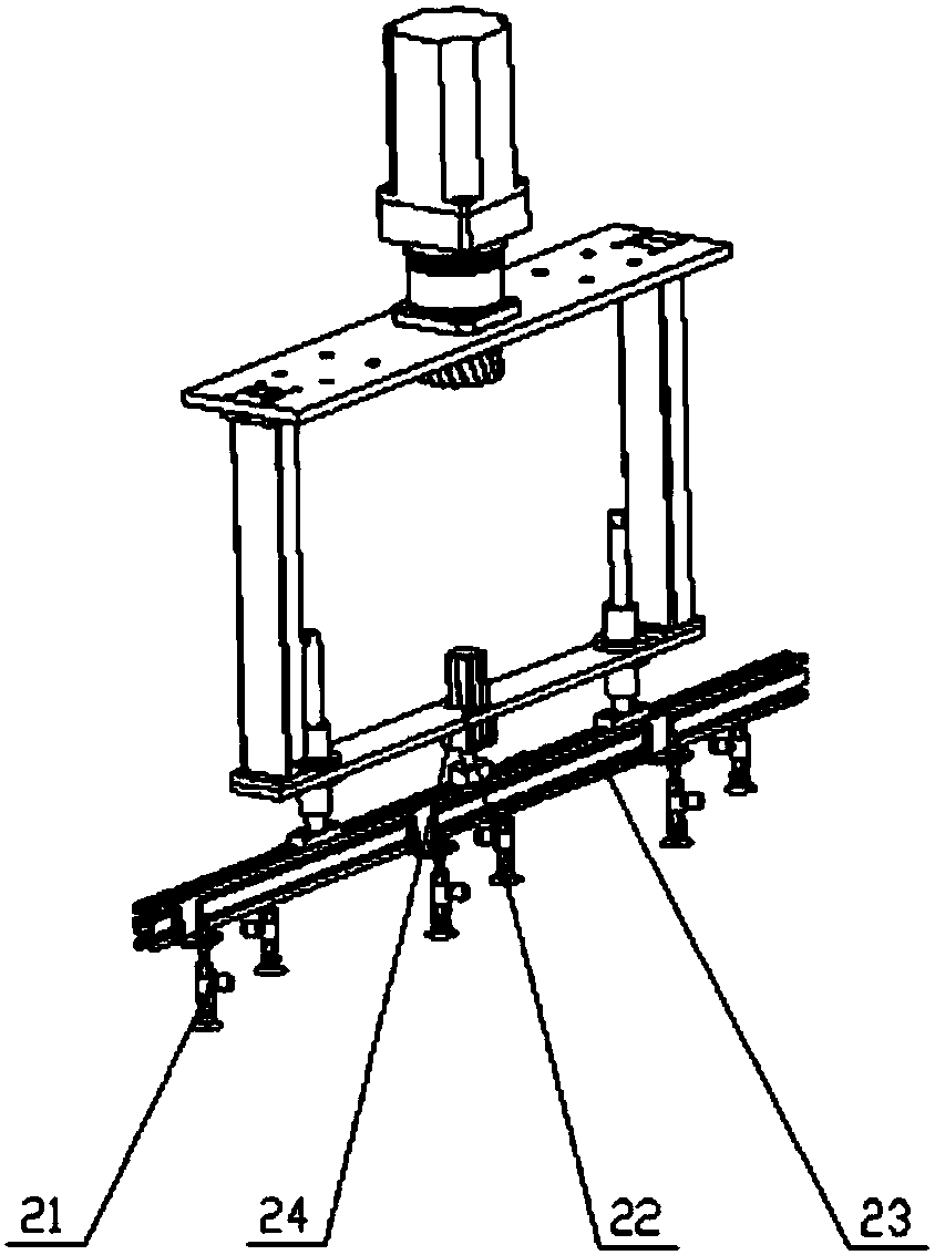
[0029] On the basis of Embodiment 1, the guide rail device 2 is composed of two parallel linear guide rail pairs, and the helical rack 3 is arranged between the two linear guide rail pairs.

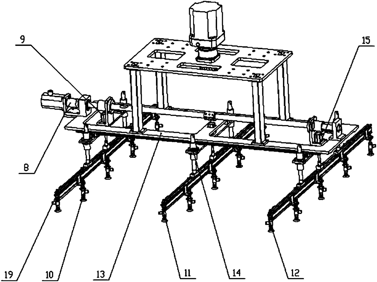
[0030] Such as figure 2 As shown, the three-column stacking 4 includes a three-column connecting plate 13, three sets of vacuum manipulators 7, a transmission device 8 for controlling the three sets of vacuum manipulators 7 to expand and contract in the X direction, and a first pneumatic device 9 to expand and contract in the Y direction. The device 9 is provided with three groups, and the three groups of vacuum manipulators 7 include the first vacuum manipulator 10, the second vacuum manipulator 11 and the third vacuum manipulator 12 parallel to each other, the first vacuum manipulator 10, the second vacuum manipulator 11 and the third vacuum manipulator 10. The vacuum manipulators 12 are respectively connected to a group of first pneumatic devices 9 through the first beam 19, and the t...


PUM


Abstract

The invention provides a full automatic lamination device for a Chinese character "Ri" shaped type or E1 type iron core of a transformer. The full automatic lamination device at least comprises a lamination frame, a guide rail device and a screw rack which are fixed above the lamination frame and parallel to each other, a three-column lamination, a yoke column lamination and an upper yoke column lamination which move along the guide rail device and the screw rack; the three-column lamination, the yoke column lamination and the upper yoke column lamination are located on the same straight line and respectively connected with the guide rail device; the three-column lamination, the yoke column lamination and the upper yoke column lamination are respectively driven by a group of servo systems and a helical gear; the three-column lamination is provided with a transmission used for adjusting the edge distance of the transformer iron core; the three-column lamination, the yoke column lamination and the upper yoke column lamination are linearly stacked by means of intermediate alternating; left and right laminated reclaiming is adopted, the structure is compact and the efficiency is high, the lamination technological requirement on the Chinese character "Ri" shaped type or E1 type iron core of different transformer manufactures can be satisfied, and manual tedious labor can be replaced, thereby saving time and labor, realizing full automatic lamination and having strong universality.

Description

technical field [0001] The invention belongs to the field of transformer iron core production, and mainly relates to a fully automatic lamination device for transformer Japanese-shaped or E1-shaped iron cores. Background technique [0002] The "day"-shaped iron core is a relatively common iron core form in the transformer industry. The reason why it is stacked into the "day" character is to facilitate the detection of loss. After the inspection is completed, the upper yoke column is removed as a whole to form an "E" shape, and the next step process. This equipment can not only complete the stacking of "Japanese" type iron cores, but also complete the stacking of "E1" type iron cores. The so-called "E1" type means that three side columns and one yoke column are combined to form an E shape, and then the upper yoke columns are stacked separately for subsequent insertion, and finally combined into an "E1" type core, which is gradually stacked in a single layer until The requir...

Claims


Application Information

Patent Timeline
Patent Type & Authority Patents(China)
IPC IPC(8): H01F41/02B25J9/14B25J15/06
CPCB25J9/144B25J15/0616H01F41/0233
Inventor 张智臻赵丹张华杰谢彦明闫超虎王晨
Owner CECEP ENVIRONMENTAL PROTECTION EQUIP CO LTD
Learn More