Electromagnetic clutch with wire-driven friction and meshing transmission joint device

A technology of transmission engagement and clutch, applied in the field of clutches, can solve the problems of high power consumption, large volume, high cost, etc., and achieve the effect of large transmission torque, high transmission efficiency and simple structure

Active Publication Date: 2017-04-26
SHANDONG UNIV OF TECH
View PDF6 Cites 5 Cited by
  • Summary
  • Abstract
  • Description
  • Claims
  • Application Information

AI Technical Summary

Problems solved by technology

When the friction plate electromagnetic clutch is engaged, the electromagnetic force generated by the electromagnetic coil energization compresses the active friction plate and the driven friction plate to transmit torque. When transmitting large torque, the radial size of the input plate and the driven plate must be increased, Large electromagnetic coil energizing current increases the number of active friction plates and driven friction plates, so there are disadvantages such as large volume, low speed, and high power consumption; the tooth-jaw electromagnetic clutch transmits large torque, and requires low speed difference when engaging, and there are The disadvantage of high power consumption; the magnetic powder clutch has a fast response and can achieve fine-tuning of the accuracy according to the current, but there are disadvantages such as high power consumption, temperature rise when the slip is large, and high cost; when the slip electromagnetic clutch is working, There must be a certain speed difference between the driving and driven parts to transmit torque, and the eddy current in the rotor will generate heat, which is proportional to the speed difference

Method used


Image

  • Electromagnetic clutch with wire-driven friction and meshing transmission joint device
  • Electromagnetic clutch with wire-driven friction and meshing transmission joint device

Examples


Embodiment Construction

[0016] The following describes the technical solutions in the embodiments of the present invention in detail with reference to the accompanying drawings in the embodiments of the present invention. Obviously, the described embodiments are only a part of the embodiments of the present invention, not all the embodiments; Embodiments, all other embodiments obtained by those of ordinary skill in the art without creative work fall within the protection scope of the present invention.

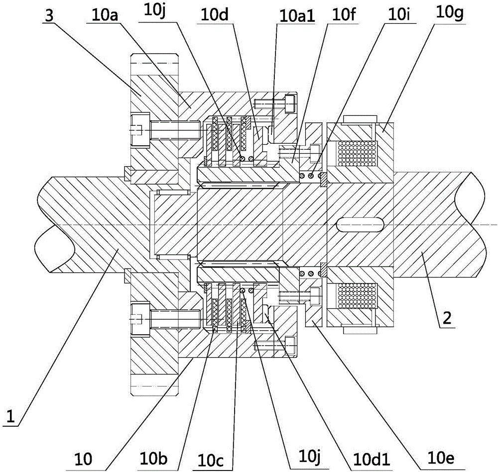
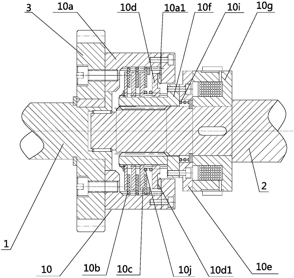
[0017] Such as figure 1 As shown, the electromagnetic clutch of the friction-by-wire and meshing transmission and engagement device of the present invention includes a clutch input shaft 1, a clutch output shaft 2, an input gear 3, and a friction-by-wire and meshing transmission and engagement device 10; the input gear 3 is fixedly mounted on the clutch Input shaft 1.

[0018] The wire-controlled friction and meshing transmission engagement device 10 includes an inner spline hub with side teeth 10a, a fri...


PUM


Abstract

The invention discloses an electromagnetic clutch with a wire-driven friction and meshing transmission joint device. When a solenoid coil is not electrified, under the action of a return spring, an internal splined hub with lateral teeth and a spline coupling with lateral teeth are not in meshing transmission, and the clutch is in a disengaged state; and when the solenoid coil is electrified, under the action of an electromagnetic force, a spline housing overcomes the elastic force of the return spring and moves toward an electromagnet, and the internal splined hub with lateral teeth and the spline coupling with lateral teeth are in meshing transmission, so that synchronous transmission of the internal splined hub with lateral teeth and the spline housing is realized, and the clutch is engaged.

Description

Technical field [0001] The invention relates to a clutch, more specifically an electromagnetic clutch of a wire-controlled friction and meshing transmission engagement device. Background technique [0002] The existing electromagnetic clutches can be divided into: friction plate type electromagnetic clutch, jaw type electromagnetic clutch, magnetic powder clutch, slip type electromagnetic clutch and so on. When the friction plate electromagnetic clutch is engaged, the electromagnetic force generated by the energization of the electromagnetic coil compresses the friction force generated by the active friction plate and the driven friction plate to transmit torque. When transmitting large torque, the radial size of the input disk and the driven disk must be increased. The large electromagnetic coil energizes the current and increases the number of active and driven friction plates, so it has the disadvantages of large volume, low speed and high power consumption; the jaw type elect...

Claims


Application Information

Patent Timeline
Patent Type & Authority Applications(China)
IPC IPC(8): F16D27/04F16D27/09F16D23/06
CPCF16D23/06F16D27/04F16D27/09F16D2023/0618F16D2023/0625F16D2023/0643F16D2023/0656
Inventor 邵金菊曲金玉王吉华任传波
Owner SHANDONG UNIV OF TECH
Why Eureka
Try Eureka