
A rail brake device

A brake device and track technology, which is applied in the direction of brakes, transportation and packaging, railway car body parts, etc., where the brake elements interact with the track, and can solve problems such as damage to sports cars or vehicles, long braking distances, and vehicles hitting obstacles.

Active Publication Date: 2019-12-10
XUZHOU LIEQI COMMERCE & TRADE CO LTD
View PDF5 Cites 0 Cited by
  • Summary
  • Abstract
  • Description
  • Claims
  • Application Information

AI Technical Summary

Problems solved by technology

[0002] The existing braking device for inclined mine cars has a long braking distance. When there are obstacles on the track, due to the long braking distance, it is easy for the vehicle to hit the obstacle, resulting in damage to the sports car or the vehicle.

Method used


Image

  • A rail brake device
  • A rail brake device

Examples


Embodiment Construction

[0011] The present invention will be described in detail below in conjunction with the accompanying drawings.

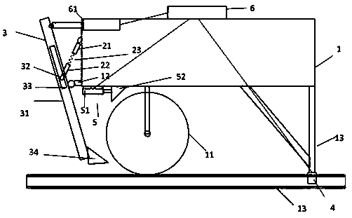
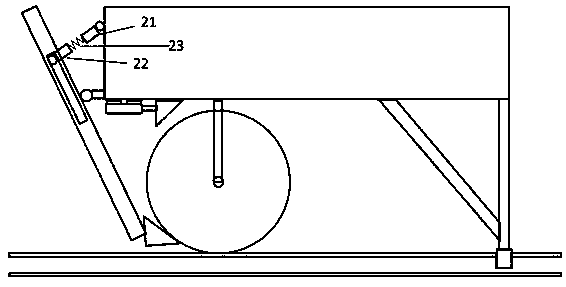
[0012] Such as figure 1 , figure 2 As shown, the rail brake device includes a vehicle frame 1, wheels 11 and rails 13, and the brake device also includes a hydraulic clamp 4 driven by hydraulic pressure at the tail end of the vehicle frame 1, and the hydraulic clamp 4 is connected to the vehicle through a tripod. The tail end of the frame 1 is connected; it also includes a brake 5 at the top of the wheel 11, which is fixed on the top of the wheel 11, and includes a hydraulic cylinder 51 whose push rod faces the wheel, and the front end of the push rod is connected with a first brake block 52; it also includes a The wheel bottom brake 3 includes a connecting rod 31 hinged to the support 12 fixed on the vehicle frame, the connecting rod 31 is located at the upper end of the support 12 and has a chute 33, and the chute 33 is slidably connected with a slider 32, The s...


PUM


Abstract

The invention relates to a baking device on tracks. The braking device comprises hydraulic pincers (4), brakes (5), and wheel bottom brakes (3), wherein the hydraulic pincers (4) are arranged at the tail end of a frame (1), are hydraulically driven, and are connected with the tail end of the frame (1) through a tripod; each of the brakes (5) is arranged at the top end of a corresponding wheel (11), is fixed on the corresponding wheel (11), and comprises a hydraulic cylinder (51); a push rod of each hydraulic cylinder (51) faces the corresponding wheel, and the front end of each of the push rods is connected with a first braking block (52); each of the wheel bottom brakes (3) comprises a connecting rod (31); each connecting rod (31) is hinged to a supporting seat (12) fixed on the frame, and a sliding groove (33) is formed in a position, at the upper end of the supporting seat (12), of each connecting rod (31), and is in sliding connection with a sliding block (32); each sliding block (32) is connected with a second connecting rod (22), and the other end of each second connecting rod (22) is fixedly connected with a spring (23); each spring (23) is fixedly connected with a third connecting rod (21); each third connecting rod (21) is hinged to the frame (1); and a second braking block (33) is fixed to the bottom end of each connecting rod (31).

Description

technical field [0001] The invention relates to a braking device for an inclined mine car. Background technique [0002] The existing braking device for inclined mine cars has a long braking distance. When there are obstacles on the track, the long braking distance may easily cause the vehicle to hit the obstacle, resulting in damage to the sports car or the vehicle. Contents of the invention [0003] The object of the present invention is to provide a mine car rail braking device with a short braking distance. [0004] To achieve the above object, the present invention includes a vehicle frame, wheels and tracks, and the brake device also includes a hydraulic clamp driven by hydraulic pressure at the rear end of the vehicle frame, and the hydraulic clamp is connected with the rear end of the vehicle frame through a tripod; It includes a brake at the top of the wheel, which is fixed above the wheel, and includes a hydraulic cylinder, whose push rod faces the wheel, and th...

Claims


Application Information

Patent Timeline
Patent Type & Authority Patents(China)
IPC IPC(8): B61H7/06B61H7/12
Inventor 时春苗
Owner XUZHOU LIEQI COMMERCE & TRADE CO LTD
Learn More