A factory purification ventilation system and its working method

A technology for ventilation systems and factories, applied in chemical instruments and methods, separation methods, dispersed particle separation, etc., can solve the problems of complicated construction, large area of ​​processing equipment, large investment, etc., and achieves strong applicability, easy replacement, The effect of saving investment

Active Publication Date: 2019-11-01
福建众辉环保设备有限公司
View PDF6 Cites 0 Cited by
  • Summary
  • Abstract
  • Description
  • Claims
  • Application Information

AI Technical Summary

Problems solved by technology

At present, most of the gas is collected and transported to an external processing device. This processing device occupies a large area, the construction is complicated, and the investment is large.

Method used


Image

  • A factory purification ventilation system and its working method

Examples


Embodiment Construction

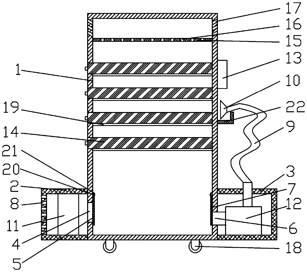
[0019] Combine below figure 1 The present invention is further described, but the protection scope of the present invention is not limited to the content.

[0020] Wherein the same components are denoted by the same reference numerals. It should be noted that the words "front", "rear", "left", "right", "upper" and "lower" used in the following description refer to the directions in the drawings, and the words "inner" and "outer "respectively refer to directions toward or away from the geometric center of a specific component, and the drawings are all in a very simplified form and use inaccurate ratios, which are only used to facilitate and clearly assist the purpose of illustrating the embodiments of the present invention.

[0021] For the sake of clarity, not all features of an actual embodiment are described. In the following description, well-known functions and constructions are not described in detail since they would obscure the invention with unnecessary detail and sho...


PUM


Abstract

The invention discloses a factory purification ventilation system, which comprises a casing, wherein a left expansion chamber casing is arranged at the left lower end of the casing; a right expansion chamber casing is arranged at the right lower end of the casing; air passing passages are arranged in a connecting position of the left expansion chamber casing and the casing and a connecting position of the right expansion chamber casing and the casing; a movable plate is arranged in the position of each air passing passage; an air inlet hole is formed in the left end of the left expansion chamber casing; the upper end of the right expansion chamber casing is connected with a gas collecting head through an air inlet hose; a left air inlet fan is arranged in the left expansion chamber casing; a right air inlet fan is arranged in the right expansion chamber casing; an active carbon adsorption drawer is arranged in the casing; the upper end of the active carbon adsorption drawer is provided with a current stabilizing plate; air passing holes are formed in the current stabilizing plate; and air outlet holes are formed in the upper ends of the left and right side walls of the casing. The factory purification ventilation system has the advantages that through the movable purification ventilation equipment, purification circulation treatment is performed in waste gas generating positions, the investment of the purification equipment is greatly reduced; the left air inlet fan can be selected to be switched on to start the fixed air suction mode, or the right air inlet fan can be selected to be switched on to start the air suction mode; and the applicability is high.

Description

technical field [0001] The invention relates to a factory purification and ventilation system and a working method thereof, belonging to the technical field of environmental protection engineering. Background technique [0002] Industrial factory buildings refer to various buildings directly used for production or supporting production, including main workshops, auxiliary buildings and ancillary facilities. Most industrial plants are equipped with a large number of production equipment. In some wood processing plants, electronic equipment processing plants, etc., a large amount of harmful gas and dust will be generated during the production process. At this time, the exhaust gas needs to be purified. At present, most of the gas is collected and transported to an external processing device, so that the processing device occupies a large area, the construction is complicated, and the investment is large. Contents of the invention [0003] The technical problem to be solved ...

Claims


Application Information

Patent Timeline
Patent Type & Authority Patents(China)
IPC IPC(8): B01D46/00B01D46/12B01D53/04
CPCB01D46/0006B01D46/12B01D53/04
Inventor 陈铭
Owner 福建众辉环保设备有限公司
Why Eureka
Try Eureka