
Brake pad of a disc brake

A technology of disc brakes and brake linings, applied in the components of brakes, brake types, friction linings, etc., can solve problems such as more expensive

Inactive Publication Date: 2017-04-19
KNORR BREMSE SYST FUER NUTZFAHRZEUGE GMBH
View PDF6 Cites 0 Cited by
  • Summary
  • Abstract
  • Description
  • Claims
  • Application Information

AI Technical Summary

Problems solved by technology

[0006] However, in order to obtain sufficient cushioning and / or insulating properties with a relatively small thickness of the intermediate layer, materials suitable for this are used, but are considerably more expensive than the materials of the friction linings

Method used


Image

  • Brake pad of a disc brake

Examples


Embodiment Construction

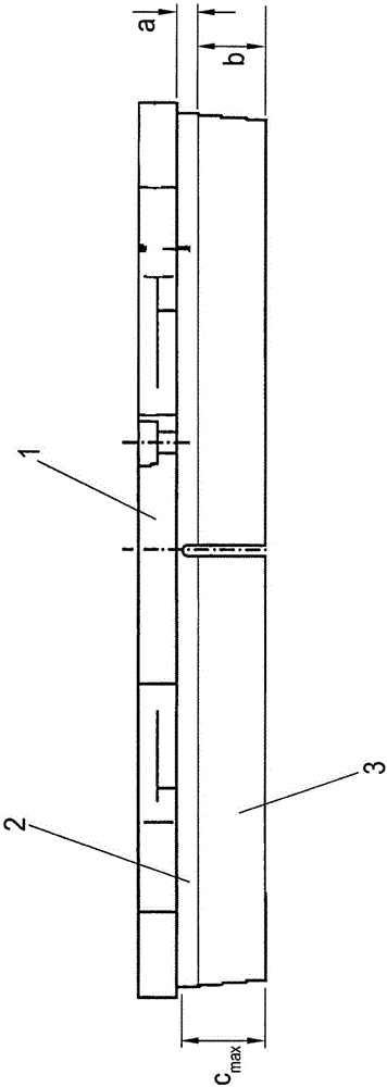
[0021] The drawing shows a brake lining of a disc brake with a lining support plate 1 made of metal or another suitable material and can be made, for example, of cast iron or metal board made.

[0022] An intermediate layer 2 is fastened to the lining support plate 1, usually by adhesive bonding and / or a form-fit connection, which carries the abrasive friction lining 3, which during operation, that is, during production contact the brake discs on the vehicle under clamping pressure when moving. The friction lining 3 is here preferably bonded to the intermediate layer in a materially bonded manner.

[0023] The brake lining shown is, so to speak, a new product, ie the friction lining 3 is unused and is at its maximum thickness b. The thickness of the intermediate layer 2 is denoted by a.

[0024] According to the invention, the thickness of the unused friction lining 3 is less than the specified maximum wear limit c max , where the thickness b of the friction lining 3 plus ...


PUM


Abstract

A brake pad of a disc brake, having a pad carrier plate (1) and an intermediate layer (2) which is fastened to the bottom surface thereof and carries an abrasive friction lining (3) is configured in such a way that the thickness (b) of the unused friction lining (3) is less than or equal to a predefined maximum wear dimension (cmax), wherein the thickness (b) of the friction lining (3) plus part of the thickness (8) of the intermediate layer (2) corresponds to the wear dimension (cmax).

Description

technical field [0001] The invention relates to a brake lining for a disc brake according to the preamble of claim 1 . Background technique [0002] Such brake linings are used in particular in disc brakes installed in commercial vehicles. In this case, such a brake lining comprises: an especially metallic lining support plate, which is made of cast iron or sheet metal; an intermediate layer fixed on the base surface of the lining support plate; friction lining, which remains on the intermediate layer. [0003] The intermediate layer primarily serves to reduce the heat transfer and to damp vibrations that occur during braking, which imply squealing noises, which are prevented by the intermediate layer. [0004] The thickness of the friction linings has hitherto been determined by a specified maximum wear limit plus a safety margin, at which point the brake lining has to be replaced as a whole. At this point, the remaining thickness of the friction lining adheres to the in...

Claims


Application Information

Patent Timeline
Patent Type & Authority Applications(China)
IPC IPC(8): F16D65/092F16D69/02F16D69/04
CPCF16D65/092F16D69/02F16D69/0408F16D2069/005F16D2069/0491F16D2200/0065F16D2069/001F16D2069/0441F16D2069/0466
Inventor D·德雷森
Owner KNORR BREMSE SYST FUER NUTZFAHRZEUGE GMBH
Learn More