Brake device with brake and method for controlling the brake

A technology of braking control and braking device, which is applied in the direction of braking transmission device, braking action starting device, foot starting device, etc., to achieve the effect of simple construction

Active Publication Date: 2019-12-13
SIEMENS MOBILITY GMBH
View PDF7 Cites 0 Cited by
  • Summary
  • Abstract
  • Description
  • Claims
  • Application Information

AI Technical Summary

Problems solved by technology

[0003] The technical problem to be solved by the invention is, in a braking device of the type given above, to always ensure in a relatively simple manner that the brakes on the one hand do not generate too high a braking force (risk of locking) and on the other hand provide a minimum braking force. Braking force (for emergency braking)

Method used


Image

  • Brake device with brake and method for controlling the brake
  • Brake device with brake and method for controlling the brake

Examples


Embodiment Construction

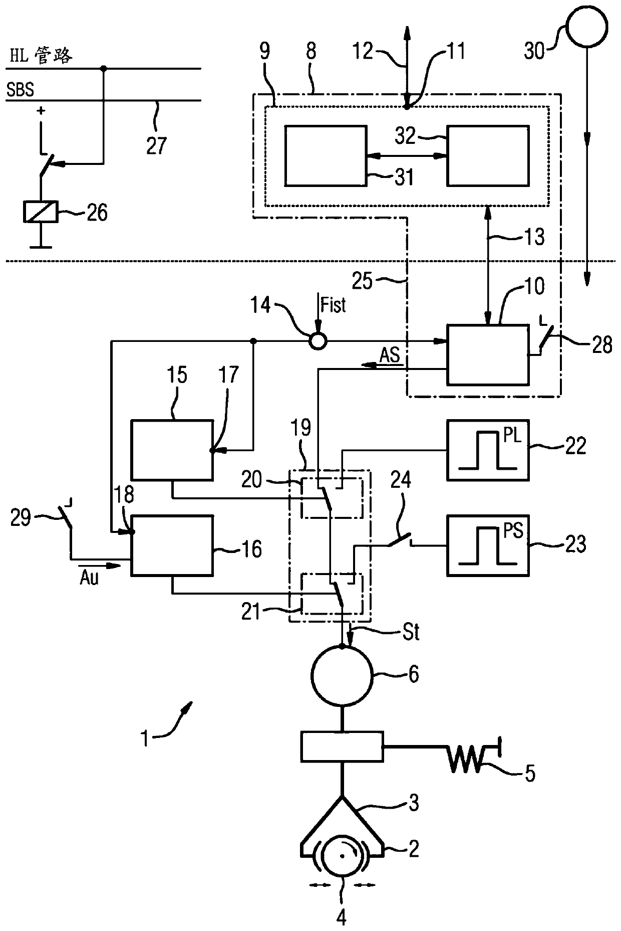
[0027] figure 1 A schematic diagram shows a brake device 1 with a brake 2 having a brake caliper 3 . The brake caliper 3 acts on a rotating component 4 to be braked, for example a brake disc, for applying a braking force. The brake 2 is fixedly connected to a body 5 by means of a suitable mechanical structure, which may be, for example, a bogie or a moving mechanism of a rail vehicle. To actuate the brake 2 , a brake driver is used, which in the example shown is an electric motor 6 . The electric motor 6 receives a control command at its input 7 and then generates a corresponding pressing force in the brake 2 .

[0028] In the exemplary embodiment shown, a control device 8 is used to generate the control commands for the electric motor 6 , which includes a central brake control device 9 and a brake control device 10 . The central brake control device 9 is installed spatially, in particular in the carriage or body of the rail vehicle, while the brake control device 10 is arr...


PUM


Abstract

The invention relates to a brake device (1) having a brake (2) and a brake control device (10) which is applied with a brake nominal variable (Fsoll) on the input side and which is connected to the brake on the output side A drive (6), which is provided with a sensor device for obtaining a brake actual variable (Fist) related to the operating state of the brake (2). In order to always ensure in this braking system in a relatively simple manner that the brakes on the one hand do not generate excessive braking forces (risk of locking) and on the other hand provide a minimum braking force (for emergency braking), according to this Invention, the brake control device (10) is connected to the brake driver (6) via the series circuit (19) of the first switching device (20) and the second switching device (21), wherein, when the brake actual parameter (Fist) exceeds the allowable When the maximum value (Fmax) of the brake is reached, the first switching device (20) can be switched from being connected to the brake control device (10) to being connected to the brake release unit (22) by the first monitoring unit (15), and when the brake When the actual parameter (Fist) is lower than the brake minimum value (Fmin), the second switching device (21) is switched from being connected to the first switching device (20) to being connected to the brake closing unit (23) by the second monitoring unit (16) connect. The invention also relates to a method for controlling a brake.

Description

technical field [0001] The invention relates to a brake device with a brake and a brake control device, which is applied with a brake nominal value on the input side and is connected to a brake drive on the output side, which brake drive is provided with a sensor device, the sensor The device is used to obtain brake actual variables which are related to the operating state of the brake. Background technique [0002] Such a braking device is shown and described in the international application WO 03 / 100282 A1. In this known braking device, the rotational angular velocity of the vehicle's wheels equipped with the brake device and the braking torque at the wheel are recorded over time; if both values ​​are zero, the vehicle is actually At rest, and the brake can be closed or remain closed. If one of these two values ​​is not equal to zero, the vehicle is in motion and the brakes must be applied urgently or must remain open. Contents of the invention [0003] The technical ...

Claims


Application Information

Patent Timeline
Patent Type & Authority Patents(China)
IPC IPC(8): B60T7/04B60T7/10B60T8/88B60T13/74B60T17/22
CPCB60T7/042B60T7/107B60T8/885B60T13/741B60T13/746B60T17/22
Inventor M.肖特L.克劳森R.罗伯茨S.詹内克T.席费尔斯
Owner SIEMENS MOBILITY GMBH
Why Eureka
Try Eureka