
Pneumatic tire

A technology of pneumatic tires and tires, which is applied to tire parts, tire treads/tread patterns, transportation and packaging, etc. It can solve the problems of deterioration of ground handling stability and low ground pressure, so as to improve handling stability Effect

Active Publication Date: 2017-04-19
THE YOKOHAMA RUBBER CO LTD
View PDF8 Cites 3 Cited by
  • Summary
  • Abstract
  • Description
  • Claims
  • Application Information

AI Technical Summary

Problems solved by technology

However, if the width of the land portion is increased excessively, the ground contact pressure at the center position in the tire width direction of the land portion will decrease.
Therefore, both ends in the circumferential direction of the tire in the vicinity of the center position are deformed toward the interior of the land portion to shorten the ground contact length, and the ground contact performance and further steering stability may deteriorate.

Method used


Image

  • Pneumatic tire
  • Pneumatic tire
  • Pneumatic tire

Examples


Embodiment

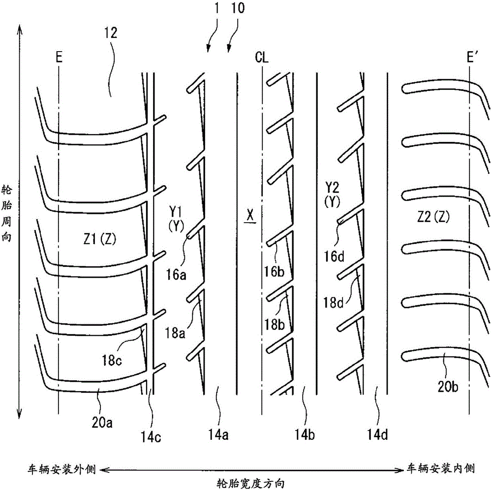
[0075] The tire size is 235 / 40ZR18 (95Y), which has the same figure 1 The tread pattern shown is an approximate tread pattern and has figure 2 ( Figure 4 ) of the tread surface contour lines PL1, PL2, PL3 of the pneumatic tires of Examples 1 to 6. In addition, the various conditions of the minute parts of the contour line of each tread surface of the pneumatic tires of Examples 1-6 are as shown in Table 1 below.

[0076] In contrast, the tire size was 235 / 40ZR18 (95Y), except figure 2 The pneumatic tire of the conventional example has the same structure as the pneumatic tire of Example 1 except that the contour lines PL1 , PL2 , and PL3 of the tread surface shown coincide with the reference contour line PL0 .

[0077] Each test tire of Example 1 to Example 6 and the conventional example produced in this way was assembled on a rim of 18×8.5J, and the air pressure was set to 230kPa, and it was mounted on a passenger car with a displacement of 2000cc. 1 (straight running p...


PUM


Abstract

The purpose of the present invention is to provide a pneumatic tire having improved operational stability performance, anti-noise / vibration performance, and anti-uneven wear performance in a well-balanced manner. In a tire meridional cross-sectional view, a profile line (PL1) of a center land portion (X) defined and formed by two center main grooves (14a, 14b) protrudes outside a reference profile line (PL0) in a tire radius direction. Profile lines (PL2, PL3) of sub-center land portions (Y1, Y2) and shoulder land portions (Z1, Z2) defined and formed in order outside the two center main grooves (14a, 14b) in the tire width direction protrude outside the reference profile line (PL0) in the tire radius direction. A pitch number (Po) of a vehicle-mount outside region and a pitch number (Pi) of a vehicle-mount inside region satisfy the relationship Po < Pi.

Description

technical field [0001] The present invention relates to a pneumatic tire having improved steering stability, noise and vibration resistance, and uneven wear resistance in a good balance. Background technique [0002] In order to improve steering stability performance, there is known a technique in which the land portion width of the tread portion is set to be large in order to ensure tread rigidity. However, if the width of the land portion is increased excessively, the ground contact pressure at the center position in the tire width direction of the land portion will decrease. Therefore, both ends of the tire in the vicinity of the center position in the circumferential direction are deformed toward the interior of the land portion to shorten the ground contact length, thereby deteriorating the ground contact performance and further steering stability. [0003] As a technology related to the improvement of steering stability accompanying the improvement of ground contact p...

Claims


Application Information

Patent Timeline
Patent Type & Authority Applications(China)
IPC IPC(8): B60C11/00B60C11/03
CPCB60C11/00B60C11/03B60C11/0311B60C2011/0388B60C2011/039B60C11/0083B60C11/0304B60C11/0318B60C11/1376
Inventor 须贺勇一
Owner THE YOKOHAMA RUBBER CO LTD
Learn More