
Wireless charging system, charging transmitting device, charging receiving device and automobile

A wireless charging and transmitting device technology, which is applied in electric vehicles, circuit devices, charging stations, etc., can solve the problems of poor vertical offset capability and horizontal offset capability, and increase the difficulty of parking for drivers, so as to improve the lateral offset capability and reduce the The effect of driver parking difficulty

Pending Publication Date: 2017-04-19
ZTEV +1
View PDF8 Cites 11 Cited by
  • Summary
  • Abstract
  • Description
  • Claims
  • Application Information

AI Technical Summary

Problems solved by technology

[0004] The offset capability of a wireless charging system is an important indicator to measure its performance. For example, the DD transformer often used in a wireless charging system is a loosely coupled transformer composed of a primary coil and a secondary coil. Due to the longitudinal offset capability of the DD transformer The defect of better and poor lateral offset ability, so the wireless charging system with this DD type transformer has the disadvantages of better longitudinal offset ability and poor lateral offset ability
For example, when parking for wireless charging, it is necessary to ensure that the primary coil and the secondary coil are facing each other or can only float within a small offset distance in the lateral direction, so as to ensure the smooth progress of wireless charging, which greatly increases Parking Difficulty

Method used


Image

  • Wireless charging system, charging transmitting device, charging receiving device and automobile
  • Wireless charging system, charging transmitting device, charging receiving device and automobile
  • Wireless charging system, charging transmitting device, charging receiving device and automobile

Examples


Embodiment Construction

[0036] The following will clearly and completely describe the technical solutions in the embodiments of the present invention with reference to the accompanying drawings in the embodiments of the present invention. Obviously, the described embodiments are only part of the embodiments of the present invention, not all of them. Based on the embodiments of the present invention, all other embodiments obtained by persons of ordinary skill in the art without creative efforts fall within the protection scope of the present invention.

[0037]It should be noted that all directional indications (such as up, down, left, right, front, back...) in the embodiments of the present invention are only used to explain the relationship between the components in a certain posture (as shown in the accompanying drawings). Relative positional relationship, movement conditions, etc., if the specific posture changes, the directional indication will also change accordingly.

[0038] In addition, the d...


PUM


Abstract

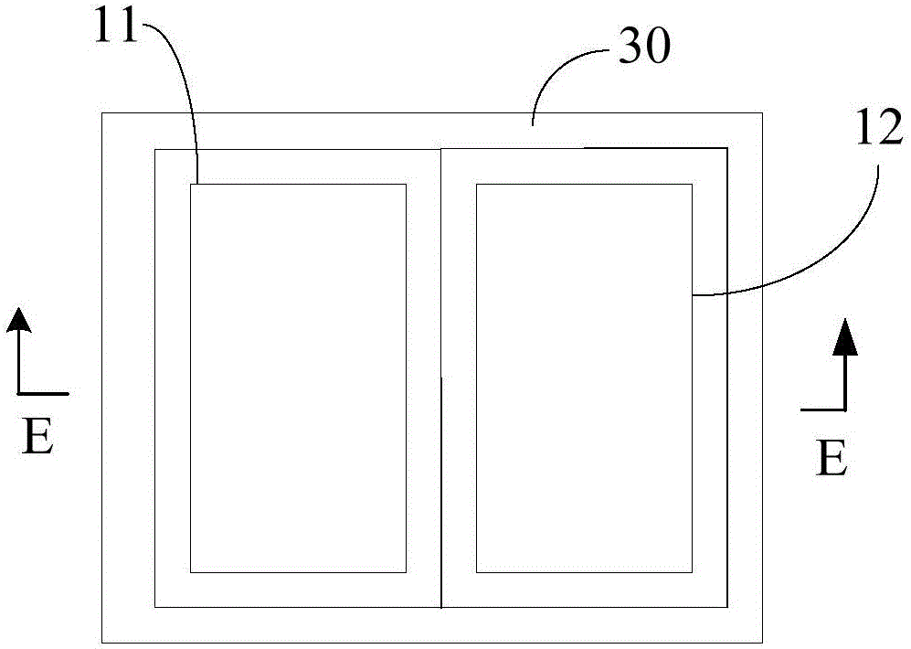
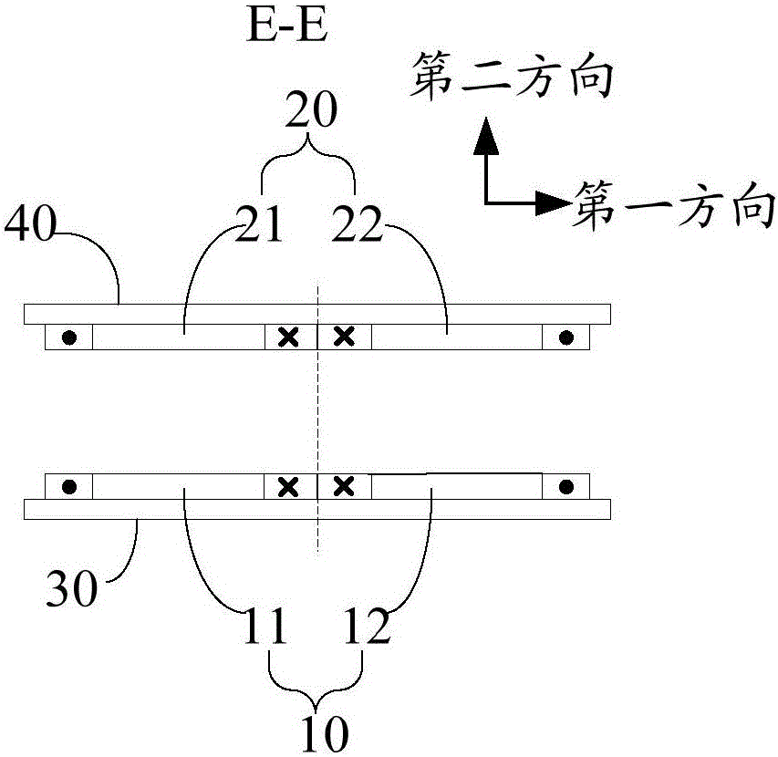
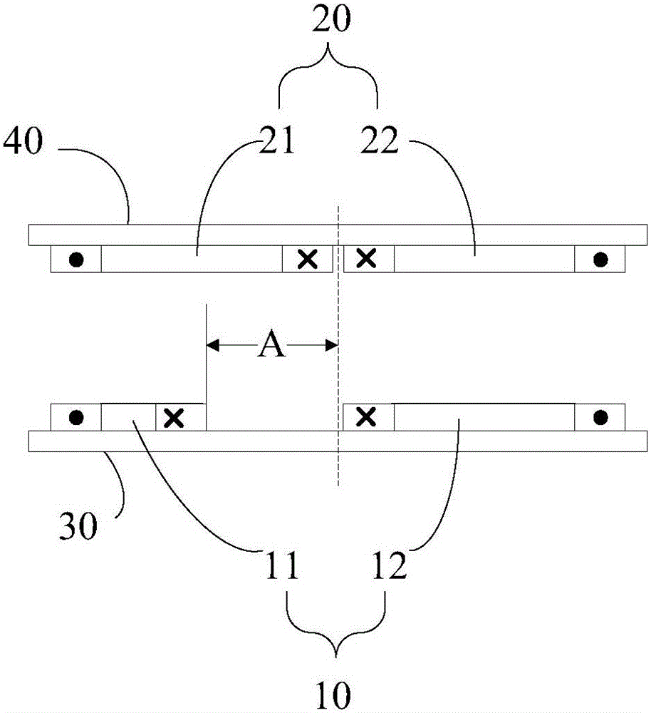
The invention discloses a wireless charging system, a charging transmitting device, a charging receiving device and an automobile. The wireless charging system comprises the charging transmitting device and the charging receiving device. The charging transmitting device comprises a primary coil which comprises a first child primary coil and a second child primary coil which are arranged in parallel in a first direction. The charging receiving device comprises a secondary coil which comprises a first child secondary coil and a second child secondary coil which are arranged in parallel in the first direction. The first child primary coil and the second child primary coil are separated by a first gap and / or the first child secondary coil and the second child secondary coil are separated by a second gap. With application of the wireless charging system, the higher lateral deviation capacity can be realized, and the parking difficulty can be effectively reduced for the driver when the wireless charging system is applied to the automobile to perform wireless charging.

Description

technical field [0001] The invention relates to the technical field of wireless charging, in particular to a wireless charging system, a charging transmitting device, a charging receiving device and an automobile. Background technique [0002] Wireless charging uses electromagnetic induction and other technologies. The charging device charges the charged device in a non-contact manner, and uses the magnetic field as the medium to realize the non-contact transmission of electric energy. Compared with wired charging, wireless charging has the advantages of less leakage, fully automatic operation and unattended operation, so it has been widely used in electric vehicle charging technology. [0003] In the prior art, a secondary coil is installed on an electric vehicle, and a primary coil is installed on a parking space of a wireless charging system. When the electric vehicle is parked at the preset charging position on the parking space, the primary coil and the secondary coil ...

Claims


Application Information

Patent Timeline
Patent Type & Authority Applications(China)
IPC IPC(8): H02J50/90B60L11/18
CPCB60L53/12B60L53/38Y02T10/70Y02T90/12Y02T10/7072Y02T90/14
Inventor 梁立科吴坤张永辉曹生辉金亮亮罗勇刘俊强赵勇
Owner ZTEV
Learn More