
Inner-ring horizontal three-dimensional braiding machine and robot core traction system

A technology of inner ring horizontal knitting machine, which is applied in braided fabrics, textiles and papermaking, etc. It can solve the problems of reduced yarn storage in the spindle, large floor space, and limited mandrel length, so as to improve the effect and reduce the floor space. area, the effect of reducing tension fluctuation

Active Publication Date: 2017-04-19
DONGHUA UNIV +1
View PDF5 Cites 19 Cited by
  • Summary
  • Abstract
  • Description
  • Claims
  • Application Information

AI Technical Summary

Problems solved by technology

[0003] This three-dimensional braiding machine has the following disadvantages due to the vertical structure: (1) because the number of braiding machine spindles directly determines the cross-sectional size of the braid, when a vertical braiding machine is used to weave a large-size preform, the number of spindles required is large, and the weaving The machine chassis is large and occupies a large area; if the size of the weaving machine chassis remains unchanged, the number of spindles can only be increased by reducing the size of the spindles, which will reduce the yarn storage capacity of the spindles, which is not conducive to the continuous weaving of large-sized preforms
(2) The traction direction of the braid of the vertical braiding machine is vertically upward, and the length of the mandrel is limited; and because the complex traction movement of the robot or manipulator is required when weaving the preform of large-sized special-shaped components, the vertical traction direction upward The weaving machine cannot be installed with the traction track of the robot or manipulator
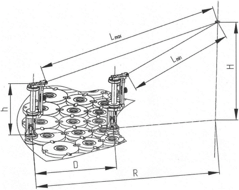
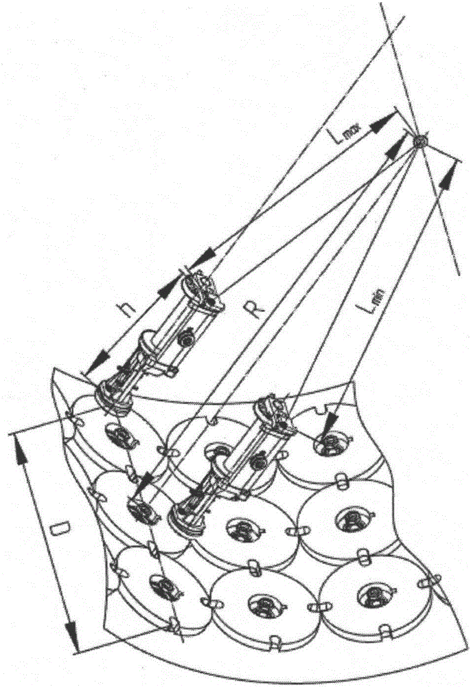
[0004] This kind of three-dimensional knitting machine has the following disadvantages due to the end surface structure: in the weaving process, the yarn tension fluctuates greatly, such as attached figure 2 And attached image 3 As shown, D is the total width of the spindle track, L min , L max Respectively, the shortest yarn length and the longest yarn length from the yarn outlet hole of the spindle to the weaving point, H is the distance from the weaving point to the center of the weaving chassis, h is the height from the yarn outlet hole of the spindle to the weaving chassis, and R is the radius of the weaving chassis

Method used


Image

  • Inner-ring horizontal three-dimensional braiding machine and robot core traction system
  • Inner-ring horizontal three-dimensional braiding machine and robot core traction system
  • Inner-ring horizontal three-dimensional braiding machine and robot core traction system

Examples


Embodiment Construction

[0034] Below in conjunction with specific embodiment, further illustrate the present invention. It should be understood that these examples are only used to illustrate the present invention and are not intended to limit the scope of the present invention. In addition, it should be understood that after reading the teachings of the present invention, those skilled in the art can make various changes or modifications to the present invention, and these equivalent forms also fall within the scope defined by the appended claims of the present application.

[0035] like Figure 4 As shown, an inner ring horizontal three-dimensional braiding machine provided by the present invention includes a braiding machine frame 4 , a braiding chassis 5 , a spindle driving component 11 , a spindle 12 , a braiding ring 7 and a braiding ring support 6 . like Image 6 As shown, a robot core mold traction system provided by the present invention includes a traction system moving base 1, a servo mo...


PUM


Abstract

The invention relates to an inner-ring horizontal three-dimensional braiding machine, which is characterized by comprising an annular braiding chassis which is vertically arranged. A spindle track is formed on the inner ring surface of the braiding chassis. A circle of spindles are distributed along the circumference of the inner ring surface of the braiding chassis. A boat-shaped block of each spindle is installed in the spindle track through a driving groove of a driving plate. Each driving plate is corresponding to a spindle driving part. A power unit drives the spindle driving part. The spindle driving part drives respective driving plate such that the driving groove of the driving plate drives the spindle to move in a staggered manner in the track. Meanwhile, axial yarn passes through a fixed mandrel of the spindle driving part. Another technical scheme of the invention is to provide a robot core traction system. The invention provides guarantees for braiding large size of complex-shape preforms. Yarn tension fluctuation is effectively reduced, and the improvement effect is more obvious during multilayer braiding.

Description

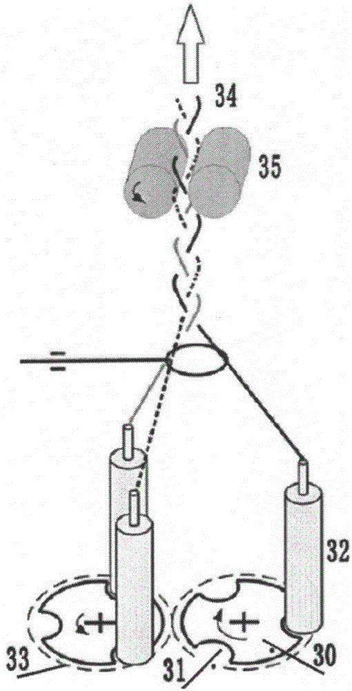
technical field [0001] The invention relates to a three-dimensional knitting machine and a mandrel traction system thereof, in particular to an inner ring horizontal three-dimensional weaving machine and a robot mandrel traction system thereof, belonging to the field of high-end textile equipment. Background technique [0002] Three-dimensional weaving is a staggered movement of the spindles in the guide grooves of the chassis of the weaving machine, so that the fibers are interwoven to obtain a three-dimensional overall structure of the braid. as attached figure 1 As shown, in general, the movement of the spindle 32 is driven by the shifting groove 31 of the dial 30, and the dial 30 only plays the role of transmitting power, and the movement of the spindle 32 is guided by the boat-shaped block at the bottom of the spindle base in the guide groove 33 of the dial 30. The motion within is realized; the motion trajectory of the spindle 32 is similar to a sinusoidal curve. Dep...

Claims


Application Information

Patent Timeline
IPC IPC(8): D04C3/00
CPCD04C3/00
Inventor 孟婥韩百峰张玉井孙以泽扈昕瞳
Owner DONGHUA UNIV
Learn More