Eureka AIR delivers breakthrough ideas for toughest innovation challenges, trusted by R&D personnel around the world.

Detection system for determining damaged parts of concrete structure by acoustic-emission computed tomography

A technology of concrete structure and tomography, which is applied in the direction of material analysis, analysis materials, instruments, etc. using acoustic wave emission technology, can solve problems such as limited projection angle, small amount of projection data, and difficulty in obtaining a complete data set for image reconstruction.

Active Publication Date: 2017-04-05
JINLING INST OF TECH
View PDF6 Cites 11 Cited by
  • Summary
  • Abstract
  • Description
  • Claims
  • Application Information

AI Technical Summary

Problems solved by technology

However, the CT algorithm requires a complete data set, and the projection data needs to be collected at equal intervals in the range of 0° to 360°, which is limited in engineering applications, especially in the field of acoustic emission. Industrial CT projection angles are limited, and the amount of projection data is small. Reconstruction is difficult to obtain a complete dataset for this case

Method used


Image

  • Detection system for determining damaged parts of concrete structure by acoustic-emission computed tomography
  • Detection system for determining damaged parts of concrete structure by acoustic-emission computed tomography
  • Detection system for determining damaged parts of concrete structure by acoustic-emission computed tomography

Examples


Embodiment Construction

[0029] In order to deepen the understanding of the present invention, the present invention will be further described below in conjunction with the accompanying drawings and embodiments, which are only used to explain the present invention and do not limit the protection scope of the present invention.

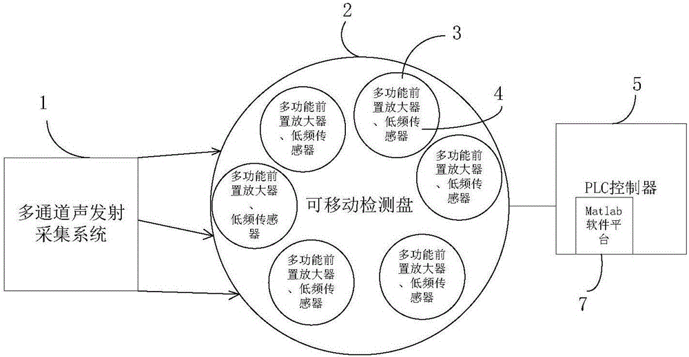
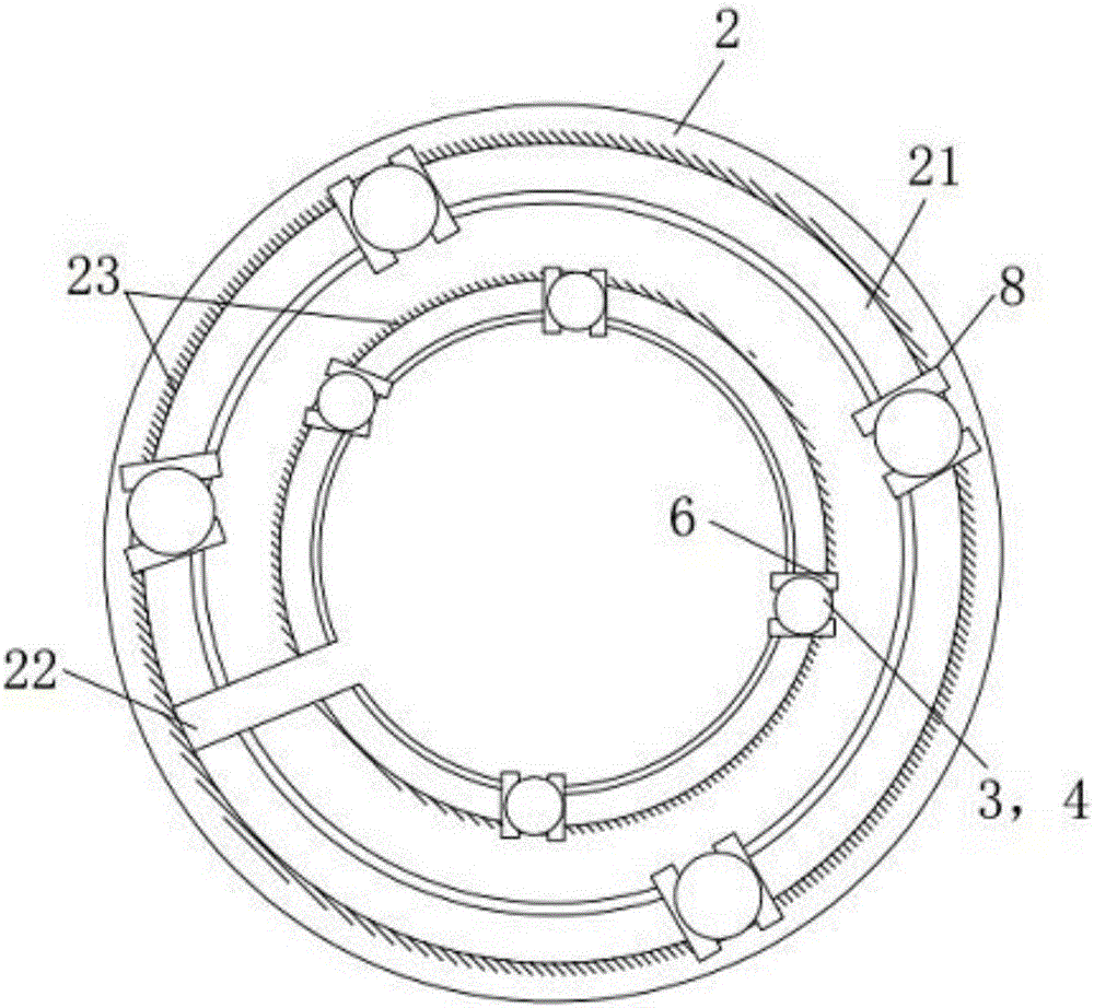
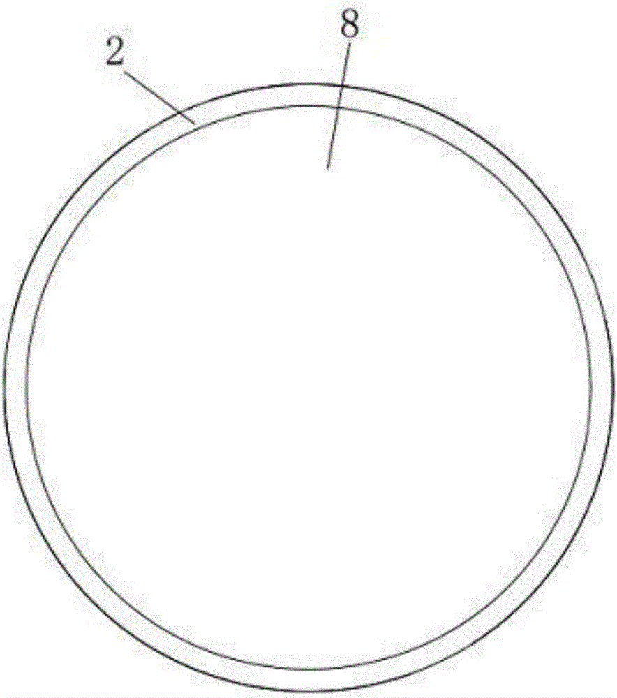
[0030] like figure 1 and figure 2 As shown, the acoustic emission tomography detection system for determining the damaged part of the concrete structure includes a multi-channel acoustic emission acquisition system 1 connected in sequence, a movable detection disk 2, and a PLC controller 5, wherein: the movable detection disk 2, one side There are 8-16 multifunctional preamplifiers 3 and low-frequency sensors 4 that are ring-shaped and arranged on the concrete structure, and a fastening device 8 is arranged on the other side; the fastening device 8 is pressed on the concrete structure, and each multiple The functional preamplifier 3 corresponds to a low-frequency sensor 4; t...


PUM


Abstract

The invention discloses a detection system for determining damaged parts of a concrete structure by acoustic-emission computed tomography. The system comprises a multichannel acoustic-emission acquisition system, a movable detection plate and a PLC controller, which are successively connected. According to the movable detection plate, one face is provided with 8-16 multifunctional preamplifiers and 8-16 low frequency sensors which are arranged in a ring array on a concrete structure, and the other face is provided with a fastening device which is compressed on the concrete structure. Each multifunctional preamplifier is corresponding to one low frequency sensor. A Matlab software platform is arranged inside the PLC controller. By using acoustic emission events as point sources, the Matlab software platform obtains slowness graphs of acoustic wave velocity variation reconstructed object structure defects according to the set ART algorithm reconstruction technique, so as to determine the damage locations of the concrete structure. According to the detection system, slowness graphs of the concrete structure in various directions can be timely obtained as much as possible through the acoustic emission technique in the concrete detection system, and each defect structure of the concrete structure can be more accurately detected.

Description

technical field [0001] The invention relates to the technical field of application of acoustic emission tomography technology in damaged parts of concrete structures, in particular to a detection system for determining damaged parts of concrete structures by acoustic emission tomography. Background technique [0002] Tomography (Computed Tomography, referred to as CT) technology (also known as computerized tomography technology) refers to the technology of reconstructing the internal (cross-section) information of the object through the data detected outside the object. Form a series of thin slices, respectively give the image of the object on each slice, and then superimpose the series of images to obtain the overall image of the interior of the object. It is a reconstruction technology from data to image, which mainly reflects the internal quality of the tested material or workpiece through the image, and conducts qualitative and quantitative analysis of defects, thereby i...

Claims


Application Information

Patent Timeline
Patent Type & Authority Applications(China)
IPC IPC(8): G01N29/14
CPCG01N29/14G01N2291/0232G01N2291/0289
Inventor 江煜许飞云
Owner JINLING INST OF TECH
Why Eureka
Eureka Blog
Learn More