Axial vent pipe structure of turbine engine and turbine engine
A technology for turbine engines and ventilation pipes, applied to engine components, machines/engines, mechanical equipment, etc., can solve the problems of increasing engine lubricating oil consumption, increasing engine lubricating oil system maintenance costs, etc.
- Summary
- Abstract
- Description
- Claims
- Application Information
AI Technical Summary
Problems solved by technology
Method used
Image
Examples
no. 1 example
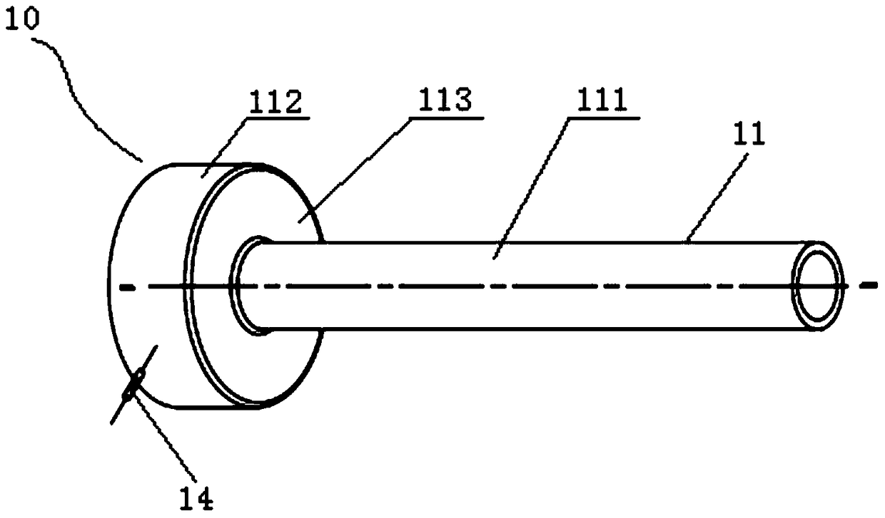
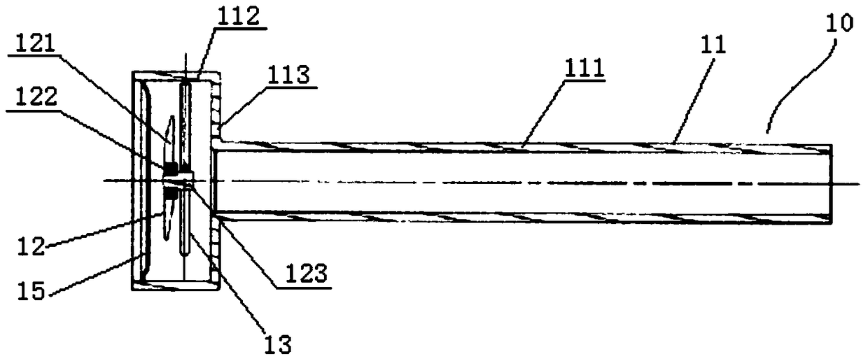
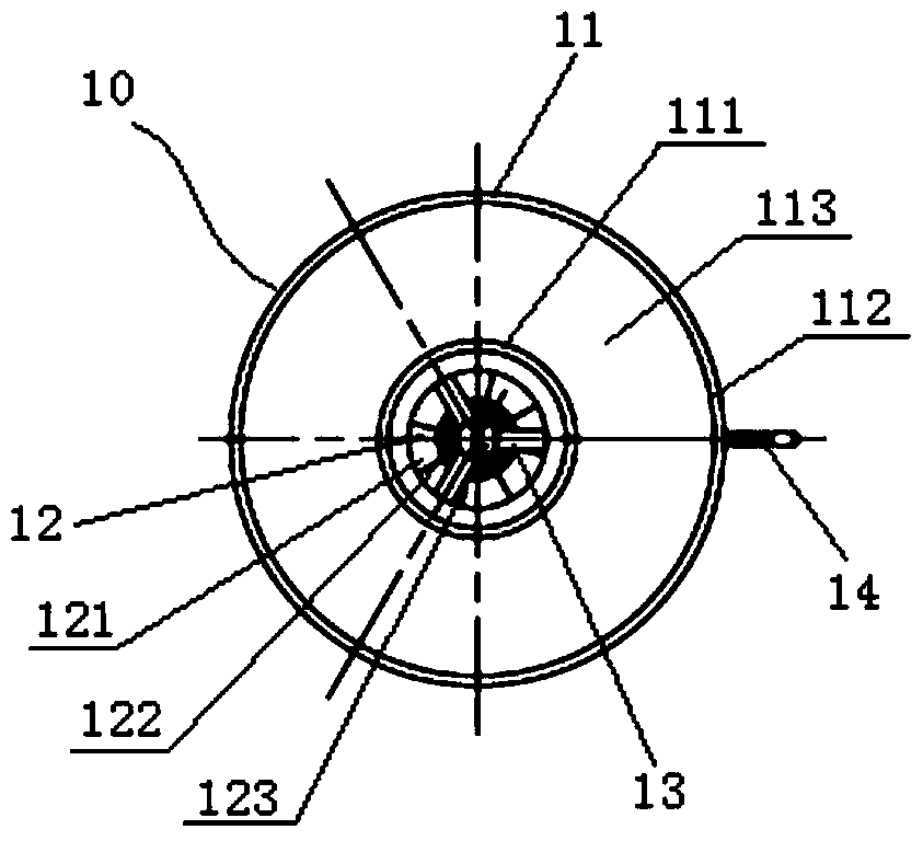
[0043] Figure 1 to Figure 4 Shown is the axial vent pipe structure of the turbine engine according to the first embodiment of the present invention. Such as Figure 1 to Figure 4 As shown, the axial ventilation pipe structure 10 of the first embodiment includes an axial ventilation pipe 11 , a wind wheel assembly 12 , a support frame 13 , an oil outlet structure and a front hollow baffle 15 . The oil outlet structure includes an oil outlet and an oil outlet pipe 14 .
[0044] Such as Figure 1 to Figure 2 As shown, the axial ventilation pipe 11 includes a main pipe section 111 , a wind wheel assembly installation pipe section 112 and a rear hollow baffle 113 . The diameter of the wind wheel assembly installation pipe section 111 is larger than the main pipe section 112 . The wind wheel assembly installation pipe section 111 and the main pipe section 112 are arranged coaxially. The wind wheel assembly installation pipe section 111 is arranged on the front side of the main...
no. 2 example
[0056] Figure 5 to Figure 8 Shown is the axial vent pipe structure of the turbine engine according to the second embodiment of the present invention. Such as Figure 5 to Figure 8 As shown, the axial ventilation pipe structure 20 of the second embodiment includes an axial ventilation pipe 21 , a wind wheel assembly 22 , a support frame 23 and an oil outlet structure. The oil outlet structure includes an oil outlet and an oil outlet pipe 24 .
[0057] Such as Figure 5 with Image 6 As shown, in the second embodiment, the axial ventilation pipe 21 includes a main pipe section 211 , a wind wheel assembly installation pipe section 212 and a rear hollow baffle 213 .
[0058] Such as Image 6 with Figure 7 As shown, in the second embodiment, the wind wheel assembly 22 includes an impeller 221 , a bearing 222 and a wheel shaft 223 . The wind wheel assembly 22 is arranged in the wind wheel assembly installation pipe section 212 through the support frame 23 , wherein the supp...
PUM
 Abstract
Description
Claims
Application Information
 - R&D
- Intellectual Property
- Life Sciences
- Materials
- Tech Scout
- Unparalleled Data Quality
- Higher Quality Content
- 60% Fewer Hallucinations
Browse by: Latest US Patents, China's latest patents, Technical Efficacy Thesaurus, Application Domain, Technology Topic, Popular Technical Reports.
© 2025 PatSnap. All rights reserved.Legal|Privacy policy|Modern Slavery Act Transparency Statement|Sitemap|About US| Contact US: help@patsnap.com


